Infrastructure Management with Terraform

Last week, my friend working in the field of infrastructure management gave me an overview of Infrastructure as Code (IaC).

He came across a tool called Terraform which can automate the deployment and management of cloud resources. Hence, together, we researched on ways to build a simple demo in order to demonstrate how Terraform can help in the cloud infrastructure management.

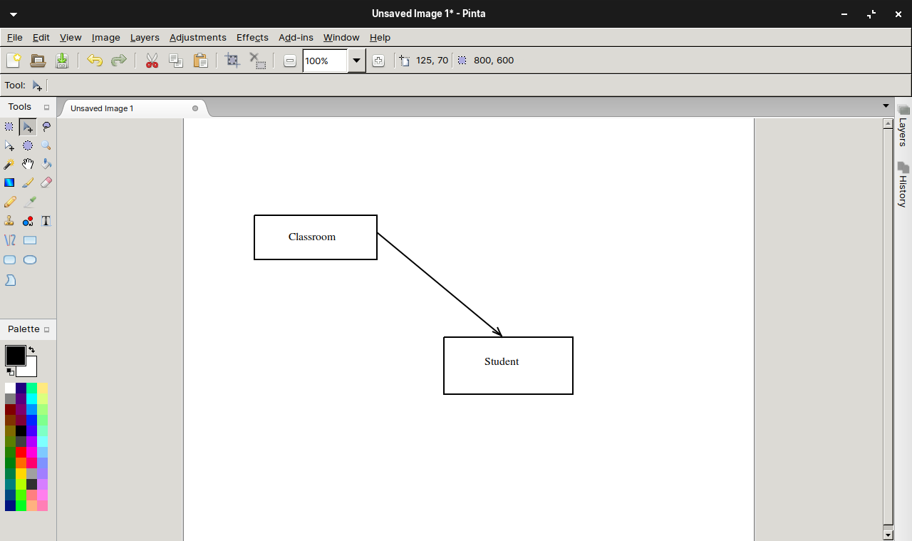
We decided to start from a simple AWS cloud architecture as demonstrated below.

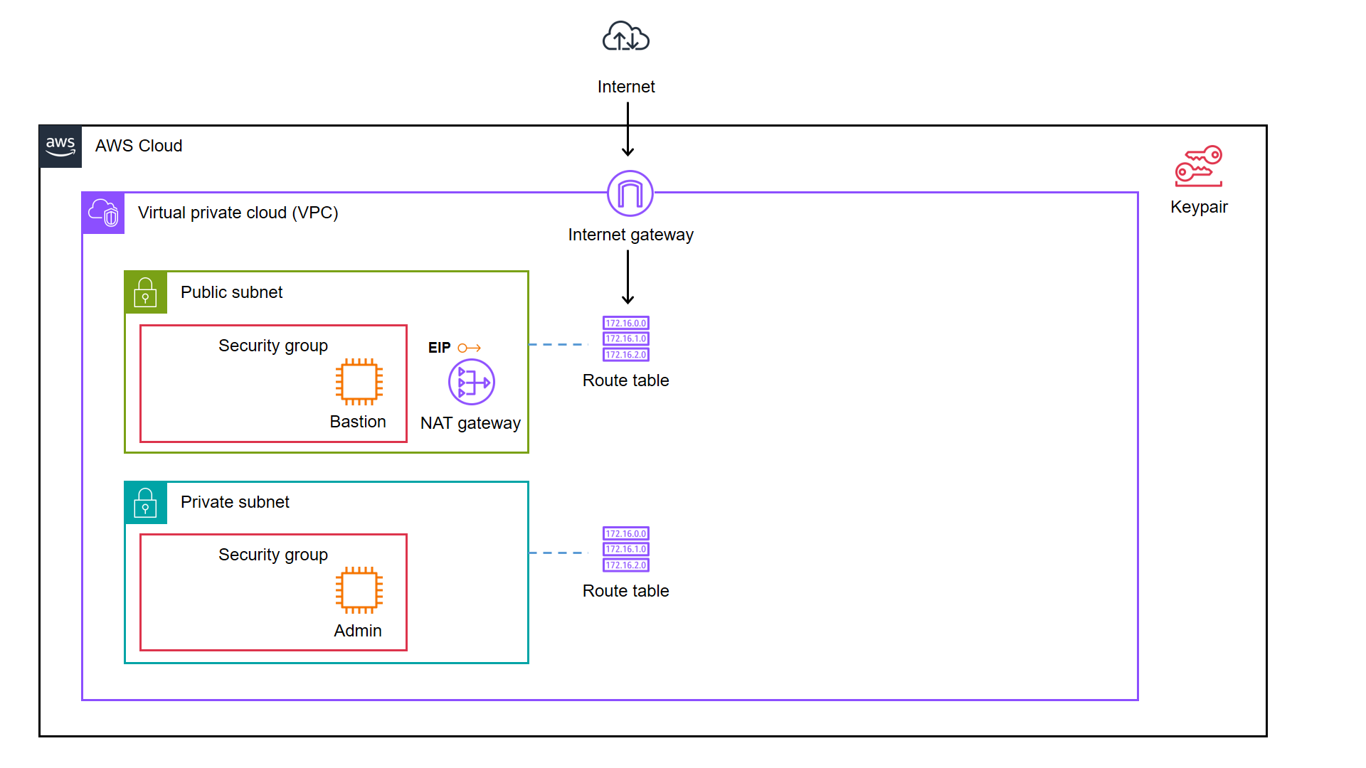
As illustrated in the diagram, we have a bastion server and an admin server.

A bastion server, aka a jump host, is a server that sits between internet network of a company and the external network, such as the Internet. It is to provide an additional layer of security by limiting the number of entry points to the internet network and allowing for strict access controls and monitoring.

An admin server, on the other hand, is a server used by system admins to manage the cloud resources. Hence the admin server typically includes tools for managing cloud resources, monitoring system performance, deploying apps, and configuring security settings. It’s generally recommended to place an admin server in a private subnet to enhance security and reduce the attack surface of our cloud infrastructure.

In combination, the two servers help to ensure that the cloud infrastructure is secure, well-managed, and highly available.

Show Me the Code!

The complete source code of this project can be found at https://github.com/goh-chunlin/terraform-bastion-and-admin-servers-on-aws.

Infrastructure as Code (IaC)

As we can see in the architecture diagram above, the cloud resources are all available on AWS. We can set them up by creating the resources one by one through the AWS Console. However, doing it manually is not efficient and it is also not easy to be repeatedly done. In fact, there will be other problems arising from doing it with AWS Console manually.

  • Manual cloud resource setup leads to higher possibility of human errors and it takes longer time relatively;
  • Difficult to identify cloud resource in use;
  • Difficult to track modifications in infrastructure;
  • Burden on infrastructure setup and configuration;
  • Redundant work is inevitable for various development environments;
  • Restriction is how only the infrastructure PIC can setup the infrastructure.

A concept known as IaC is thus introduced to solve these problems.

IaC is a way to manage our infrastructure through code in configuration files instead of through manual processes. It is thus a key DevOps practice and a component of continuous delivery.

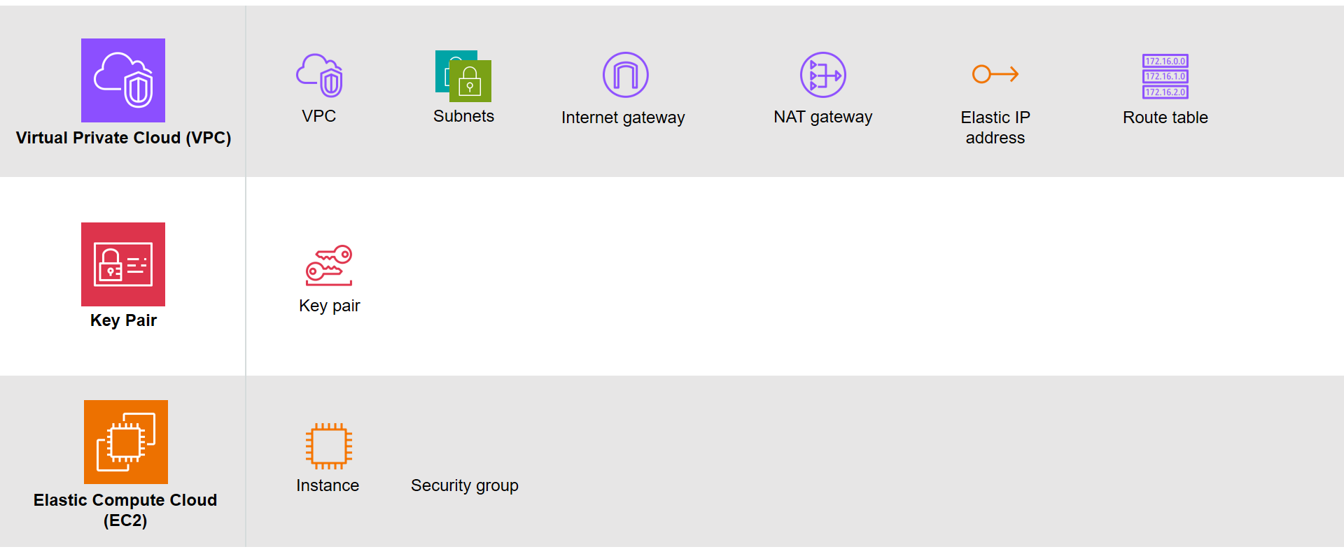
Based on the architecture diagram, the services and resources necessary for configuring with IaC can be categorised into three parts, i.e. Virtual Private Cloud (VPC), Key Pair, and Elastic Compute Cloud (EC2).

The resources necessary to be created.

There are currently many IaC tools available. The tools are categorised into two major groups, i.e. those using declarative language and those using imperative language. Terraform is one of them and it is using Hashicorp Configuration Language (HCL), a declarative language.

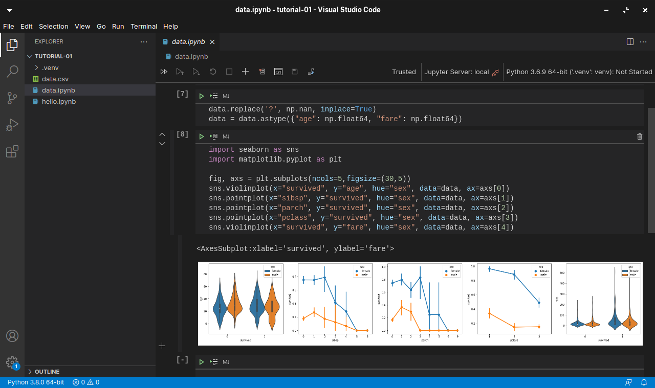
The workflow for infrastructure provisioning using Terraform can be summarised as shown in the following diagram.

The basic process of Terraform. (Credit: HashiCorp Developer)

We first write the HCL code. Then Terraform will verify the status of the code and apply it to the infrastructure if there is no issue in verification. Since Terraform is using a declarative language, it will do the identification of resources itself without the need of us to manually specify the dependency of resources, sometimes.

After command apply is executed successfully, we can check the applied infrastructure list through the command terraform state list. We can also check records of output variable we defined through the command terraform output.

When the command terraform apply is executed, a status information file called terraform.tfstate will be automatically created.

After understanding the basic process of Terraform, we proceed to write the HCL for different modules of the infrastructure.

Terraform

The components of a Terraform code written with the HCL are as follows.

Terraform code.

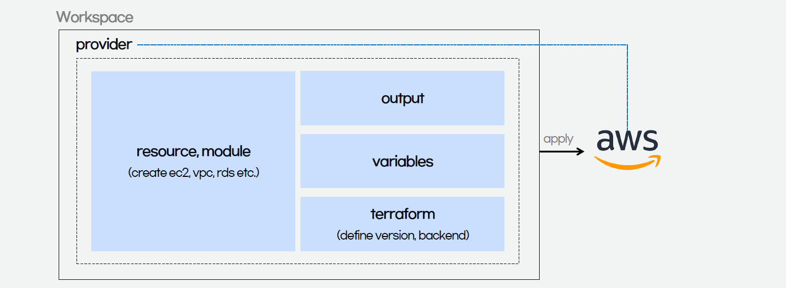
In Terraform, there are three files, i.e. main.tf, variables.tf, and outputs.tf recommended to have for a minimal module, even if they’re empty. The file main.tf should be the primary entry point. The other two files, variables.tf and outputs.tf, should contain the declarations for variables and outputs, respectively.

For variables, we have vars.tf file which defines the necessary variables and terraform.tfvars file which allocated value to the defined variables.

In the diagram above, we also see that there is a terraform block. It is to declare status info, version info, action, etc. of Terraform. For example, we use the following HCL code to set the Terraform version to use and also specify the location for storing the status info file generated by Terraform.

terraform {
  backend "s3" {
    bucket  = "my-terraform-01"
    key     = "test/terraform.tfstate"
    region  = "ap-southeast-1"
  }
  required_version = ">=1.1.3"
}

Terraform uses a state file to map real world resources to our configuration, keep track of metadata, and to improve performance for large infrastructures. The state is stored by default in a file named “terraform.tfstate”.

This is a S3 bucket we use for storing our Terraform state file.

The reason why we keep our terraform.tfstat file on the cloud, i.e. the S3 bucket, is because state is a necessary requirement for Terraform to function and thus we must make sure that it is stored in a centralised repo which cannot be easily deleted. Doing this also good for everyone in the team because they will be working with the same state so that operations will be applied to the same remote objects.

Finally, we have a provider block which declares cloud environment or provider to be created with Terraform, as shown below. Here, we will be creating our resources on AWS Singapore region.

provider "aws" {
  region = "ap-southeast-1"
}

Module 1: VPC

Firstly, in Terraform, we will have a VPC module created with resources listed below.

1.1 VPC

resource "aws_vpc" "my_simple_vpc" {
  cidr_block = "10.2.0.0/16"

  tags = {
    Name = "${var.resource_prefix}-my-vpc",
  }
}

The resource_prefix is a string to make sure all the resources created with the Terraform getting the same prefix. If your organisation has different naming rules, then feel free to change the format accordingly.

1.2 Subnets

The public subnet for the bastion server is defined as follows. The private IP of the bastion server will be in the format of 10.2.10.X. We also set the map_public_ip_on_launch to true so that instances launched into the subnet should be assigned a public IP address.

resource "aws_subnet" "public" {
  count                   = 1
  vpc_id                  = aws_vpc.my_simple_vpc.id
  availability_zone       = data.aws_availability_zones.available.names[count.index]
  cidr_block              = "10.2.1${count.index}.0/24"
  map_public_ip_on_launch = true

  tags = tomap({
    Name = "${var.resource_prefix}-public-subnet${count.index + 1}",
  })
}

The private subnet for the bastion server is defined as follows. The admin server will then have a private IP with the format of 10.2.20.X.

resource "aws_subnet" "private" {
  count                   = 1
  vpc_id                  = aws_vpc.my_simple_vpc.id
  availability_zone       = data.aws_availability_zones.available.names[count.index]
  cidr_block              = "10.2.2${count.index}.0/24"
  map_public_ip_on_launch = false

  tags = tomap({
    Name = "${var.resource_prefix}-private-subnet${count.index + 1}",
  })
}

The aws_availability_zones data source is part of the AWS provider and retrieves a list of availability zones based on the arguments supplied. Here, we make the public subnet and private subnet to be in the same first availability zones.

1.3 Internet Gateway

Normally, if we create an internet gateway via AWS console, for example, we will sometimes forget to associate it with the VPC. With Terraform, we can do the association in the code and thus reduce the chance of setting up the internet gateway wrongly.

resource "aws_internet_gateway" "igw" {
  vpc_id = aws_vpc.my_simple_vpc.id

  tags = {
    Name = "${var.resource_prefix}-igw"
  }
}

1.4 NAT Gateway

Even though Terraform is a declarative language, i.e. a language describing an intended goal rather than the steps to reach that goal, we can use the depends_on meta-argument to handle hidden resource or module dependencies that Terraform cannot automatically infer.

resource "aws_nat_gateway" "nat_gateway" {
  allocation_id = aws_eip.nat.id
  subnet_id     = element(aws_subnet.public.*.id, 0)
  depends_on    = [aws_internet_gateway.igw]

  tags = {
    Name = "${var.resource_prefix}-nat-gw"
  }
}

1.5 Elastic IP (EIP)

If you have noticed, in the NAT gateway definition above, we have assigned a public IP to it using EIP. Since Terraform is declarative, the ordering of blocks is generally not significant. So we can define the EIP after the NAT gateway.

resource "aws_eip" "nat" {
  vpc        = true
  depends_on = [aws_internet_gateway.igw]

  tags = {
    Name = "${var.resource_prefix}-NAT"
  }
}

1.6 Route Tables

Finally, we just need to link the resources above with both public and private route tables, as defined below.

resource "aws_route_table" "public_route" {
  vpc_id = aws_vpc.my_simple_vpc.id
  route {
    cidr_block = "0.0.0.0/0"
    gateway_id = aws_internet_gateway.igw.id
  }

  tags = {
    Name = "${var.resource_prefix}-public-route"
  }
}

resource "aws_route_table_association" "public_route" {
  count          = 1
  subnet_id      = aws_subnet.public.*.id[count.index]
  route_table_id = aws_route_table.public_route.id
}

resource "aws_route_table" "private_route" {
  vpc_id = aws_vpc.my_simple_vpc.id
  route {
    cidr_block     = "0.0.0.0/0"
    nat_gateway_id = aws_nat_gateway.nat_gateway.id
  }

  tags = {
    Name = "${var.resource_prefix}-private-route",
  }
}

resource "aws_route_table_association" "private_route" {
  count          = 1
  subnet_id      = aws_subnet.private.*.id[count.index]
  route_table_id = aws_route_table.private_route.id
}

That’s all we need to do the setup the VPC on AWS as illustrated in the diagram.

MODULE 2: Key pair

Before we move on the create the two instances, we will need to define a key pair. A key pair is a set of security credentials that we use to prove our identity when connecting to an EC2 instance. Hence, we need to ensure that we have access to the selected key pair before we launch the instances.

If we are doing this on the AWS Console, we will be seeing this part on the console as shown below.

The GUI on the AWS Console to create a new key pair.

So, we can use the same info to define the key pair.

resource "tls_private_key" "instance_key" {
  algorithm = "RSA"
}

resource "aws_key_pair" "generated_key" {
  key_name = var.keypair_name
  public_key = tls_private_key.instance_key.public_key_openssh
  depends_on = [
    tls_private_key.instance_key
  ]
}

resource "local_file" "key" {
  content = tls_private_key.instance_key.private_key_pem
  filename = "${var.keypair_name}.pem"
  file_permission ="0400"
  depends_on = [
    tls_private_key.instance_key
  ]
}

The tls_private_key is to create a PEM (and OpenSSH) formatted private key. This is not a recommended way for production because it will generate the private key file and keep it unencrypted in the directory where we run the Terraform commands. Instead, we should generate the private key file outside of Terraform and distribute it securely to the system where Terraform will be run.

MODULE 3: EC2

Once we have the key pair, we can finally move on to define how the bastion and admin servers can be created. We can define a module for the servers as follows.

resource "aws_instance" "linux_server" {
  ami                         = var.ami
  instance_type               = var.instance_type
  subnet_id                   = var.subnet_id
  associate_public_ip_address = var.is_in_public_subnet
  key_name                    = var.key_name
  vpc_security_group_ids      = [ aws_security_group.linux_server_security_group.id ]
  tags = {
    Name = var.server_name
  }
  user_data = var.user_data
}

resource "aws_security_group" "linux_server_security_group" {
  name         = var.security_group.name
  description  = var.security_group.description
  vpc_id       = var.vpc_id
 
  ingress {
    description = "SSH inbound"
    from_port = 22
    to_port = 22
    protocol = "tcp"
    cidr_blocks = ["0.0.0.0/0"]
  }
  
  egress {
    description = "Allow All egress rule"
    from_port = 0
    to_port = 0
    protocol = "-1"
    cidr_blocks = ["0.0.0.0/0"]
  }
 
  tags = {
    Name = var.security_group.name
  }
}

By default, AWS creates an ALLOW ALL egress rule when creating a new security group inside of a VPC. However, Terraform will remove this default rule, and require us to specifically re-create it if we desire that rule. Hence that is why we need to include the protocol=”-1″ egress block above.

The output.tf of EC2 instance module is defined as follows.

output "instance_public_ip" {
  description = "Public IP address of the EC2 instance."
  value       = aws_instance.linux_server.public_ip
}

output "instance_private_ip" {
  description = "Private IP address of the EC2 instance in the VPC."
  value       = aws_instance.linux_server.private_ip
}

With this definition, once the Terraform workflow is completed, the public IP of our bastion server and the private IP of our admin server will be displayed. We can then easily use these two IPs to connect to the servers.

Main Configuration

With all the above modules, we can finally define our AWS infrastructure using the following main.tf.

module "vpc" {
  source          = "./vpc_module"
  resource_prefix = var.resource_prefix
}
  
module "keypair" {
  source              = "./keypair_module"
  keypair_name        = "my_keypair"
}
    
module "ec2_bastion" {
  source              = "./ec2_module"
  ami                 = "ami-062550af7b9fa7d05"       # Ubuntu 20.04 LTS (HVM), SSD Volume Type
  instance_type       = "t2.micro"
  server_name         = "bastion_server"
  subnet_id           = module.vpc.public_subnet_ids[0]
  is_in_public_subnet = true
  key_name            = module.keypair.key_name
  security_group      = {
    name        = "bastion_sg"
    description = "This firewall allows SSH"
  }
  vpc_id              = module.vpc.vpc_id
}
    
module "ec2_admin" {
  source              = "./ec2_module"
  ami                 = "ami-062550af7b9fa7d05"       # Ubuntu 20.04 LTS (HVM), SSD Volume Type
  instance_type       = "t2.micro"
  server_name         = "admin_server"
  subnet_id           = module.vpc.private_subnet_ids[0]
  is_in_public_subnet = false
  key_name            = module.keypair.key_name
  security_group      = {
    name        = "admin_sg"
    description = "This firewall allows SSH"
  }
  user_data           = "${file("admin_server_init.sh")}"
  vpc_id              = module.vpc.vpc_id
  depends_on          = [module.vpc.aws_route_table_association]
}

Here, we will pre-install the AWS Command Line Interface (AWS CLI) in the admin server. Hence, we have the following script in the admin_server_init.sh file. The script will be run when the admin server is launched.

#!/bin/bash
sudo apt-get update
sudo apt-get install -y awscli

However, since the script above will be downloading AWS CLI from the Internet, we need to make sure that the routing from private network to the Internet via the NAT gateway is already done. Instead of using the depends_on meta-argument directly on the module, which will have side effect, we choose to use a recommended way, i.e. expression references.

Expression references let Terraform understand which value the reference derives from and avoid planning changes if that particular value hasn’t changed, even if other parts of the upstream object have planned changes.

Thus, I made the change accordingly with expression references. In the change, I forced the description of security group which the admin server depends on to use the the private route table association ID returned from the VPC module. Doing so will make sure that the admin server is created only after the private route table is setup properly.

With expression references, we force the admin server to be created at a later time, as compared to the bastion server.

If we don’t force the admin_server to be created after the private route table is completed, the script may fail and we can find the error logs at /var/log/cloud-init-output.log on the admin server. In addition, please remember that even though terraform apply runs just fine without any error, it does not mean user_data script is run successfully without any error as well. This is because Terraform knows nothing about the status of user_data script.

We can find the error in the log file cloud-init-output.log in the admin server.

Demo

With the Terraform files ready, now we can move on to go through the Terraform workflow using the commands.

Before we begin, besides installing Terraform, since we will deploy the infrastructure on AWS, we also shall configure the AWS CLI using the following command on the machine where we will run the Terraform commands.

aws configure

Once it is done then only we can move on to the following steps.

Firstly, we need to download plug-in necessary for the defined provider, backend, etc.

Initialising Terraform with the command terraform init.

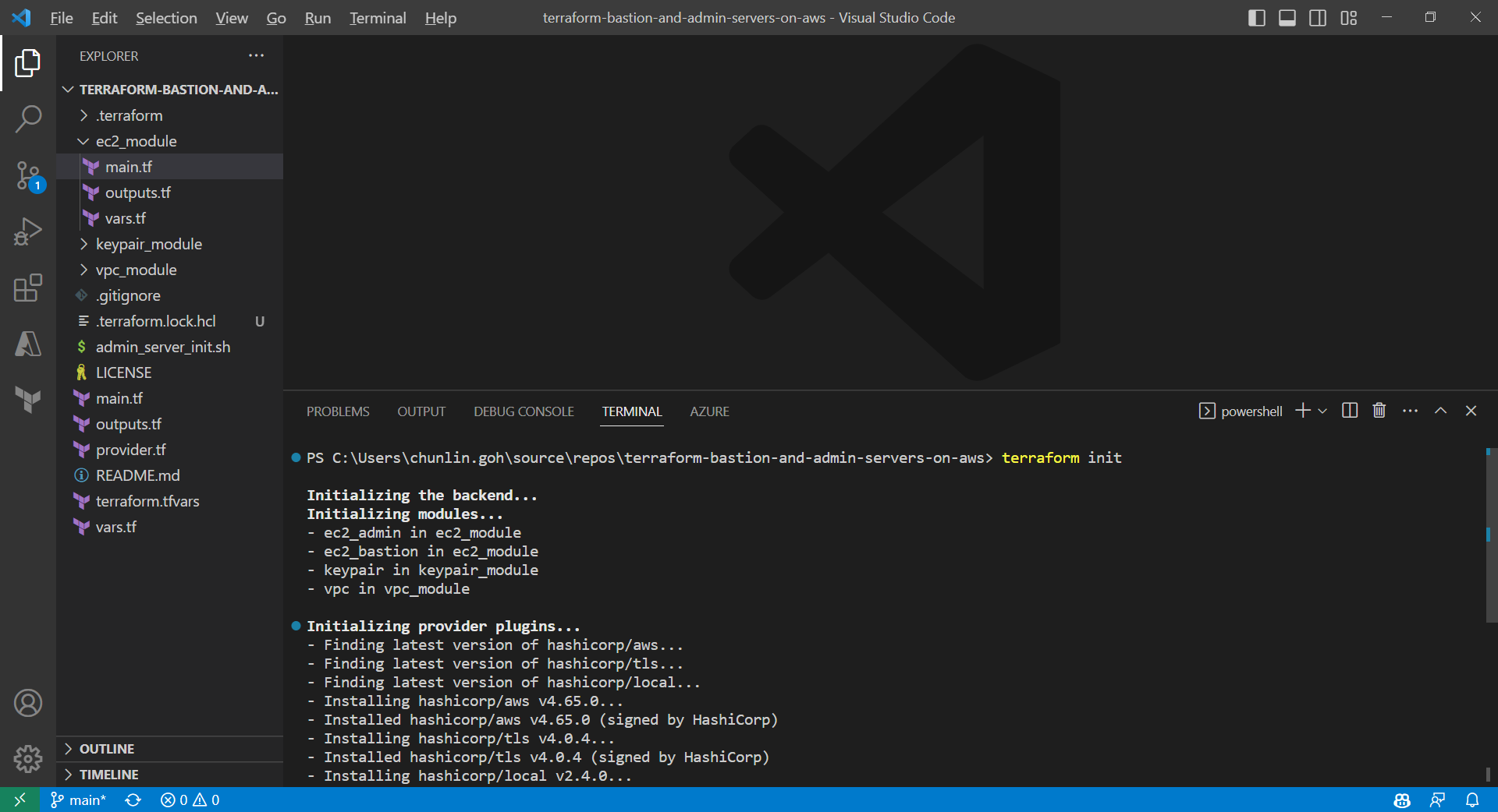
After it is successful, there will be a message saying “Terraform has been successfully initialized!” A hidden .terraform directory, which Terraform uses to manage cached provider plugins and modules, will be automatically created.

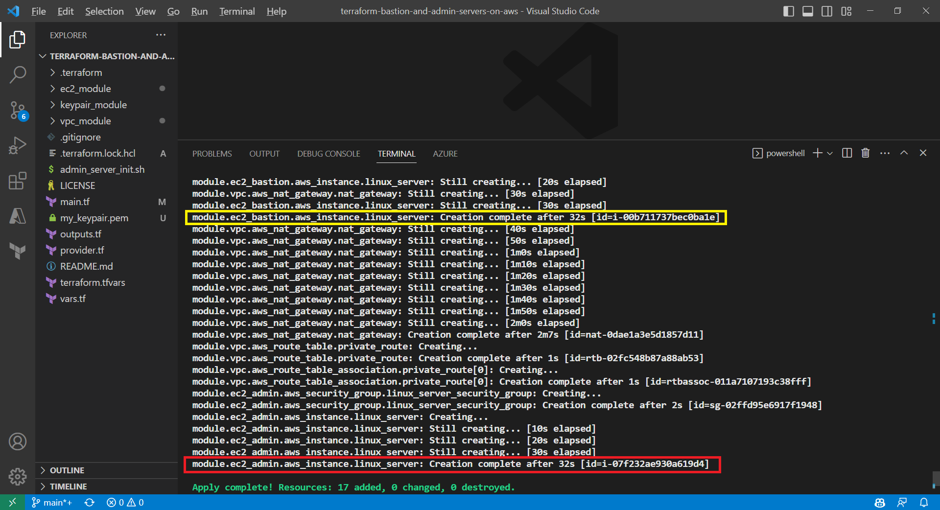
Only after initialisation is completed, we can execute other commands, like terraform plan.

Result of executing the command terraform plan.

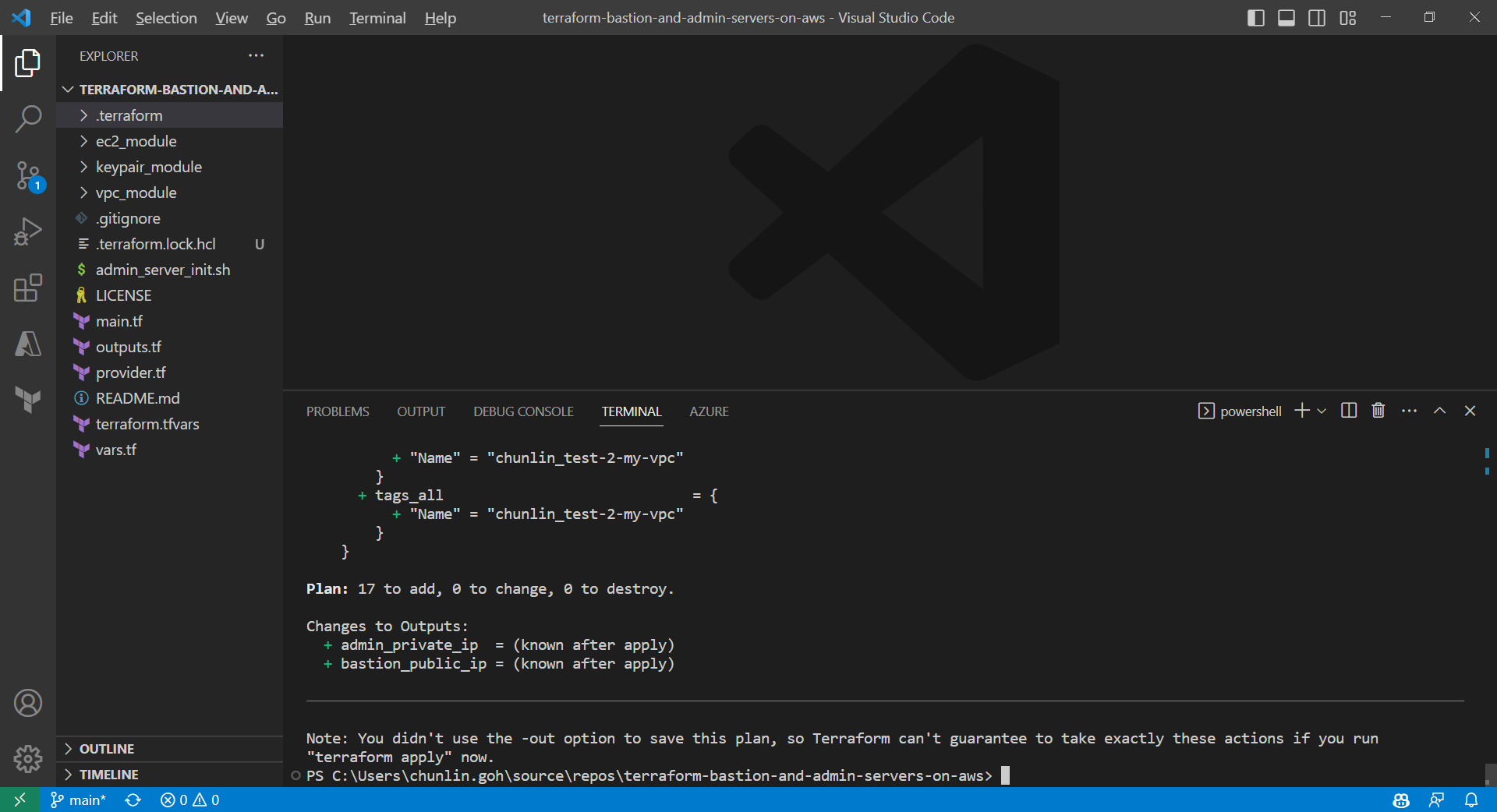
After running the command terraform plan, as shown in the screenshot above, we know that there are in total 17 resources to be added and two outputs, i.e. the two IPs of the two servers, will be generated.

Apply is successfully completed. All 17 resources added to AWS.

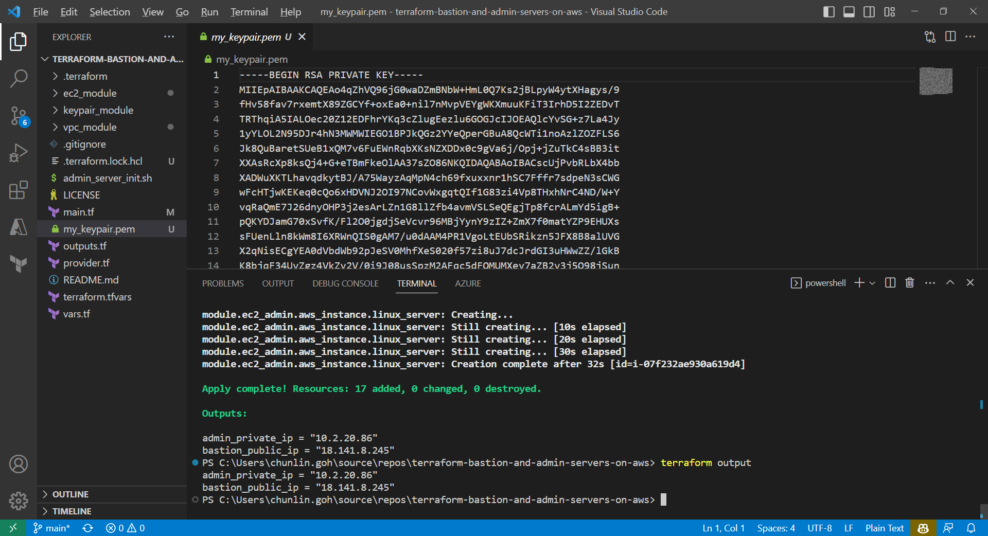
We can also run the command terraform output to get the two IPs. Meanwhile, we can also find the my_keypair.pem file which is generated by the tls_private_key we defined earlier.

The PEM file is generated by Terraform.

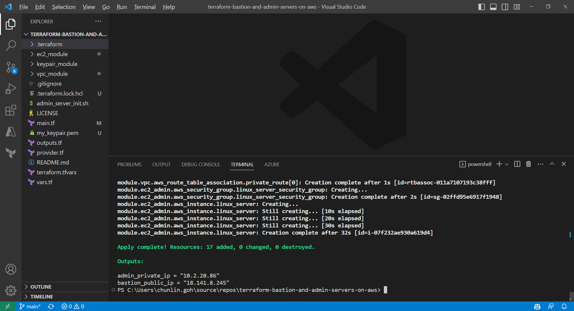
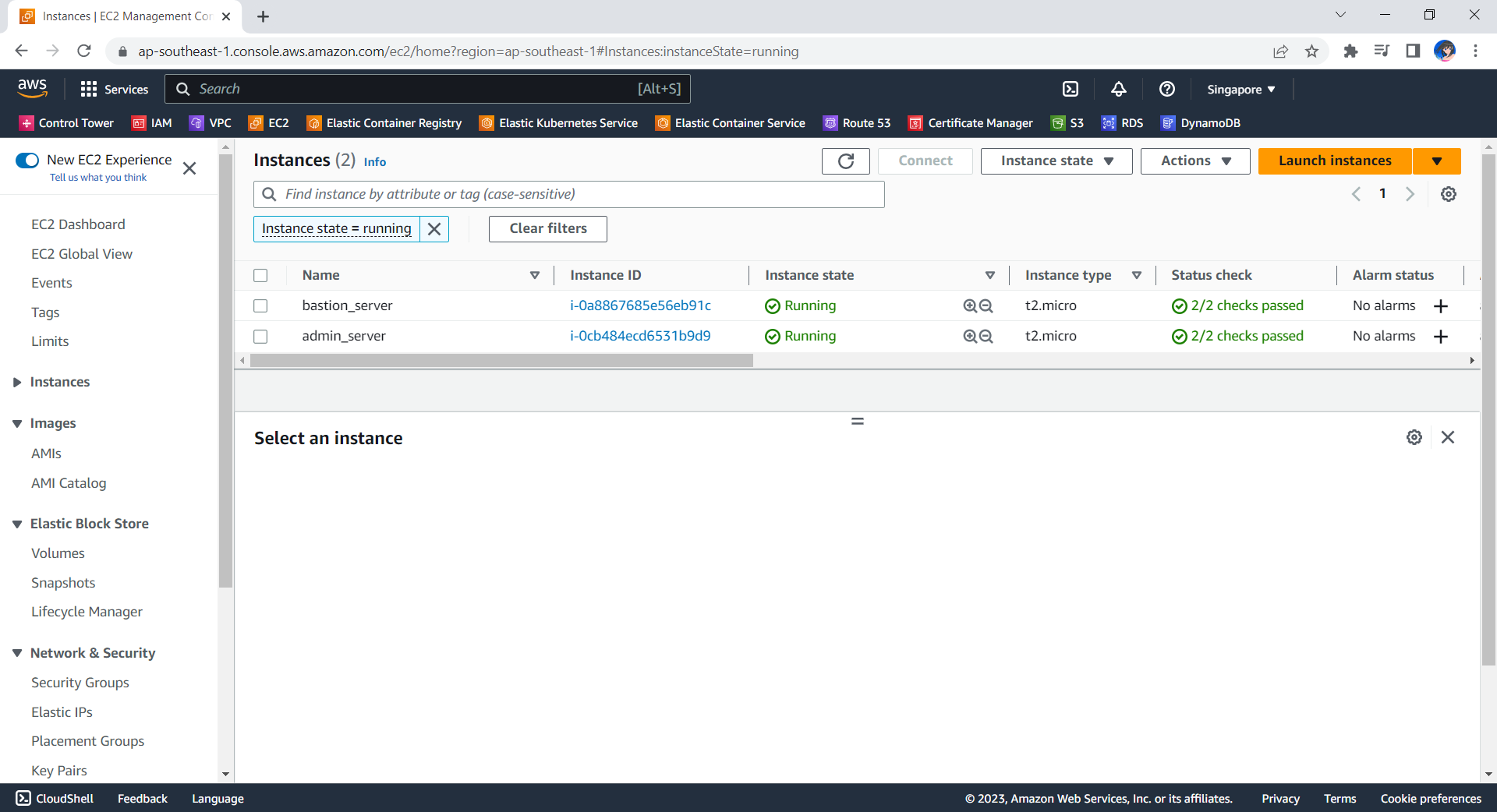
Now, if we check the resources, such as the two EC2 instances, on AWS Console, we should see they are all there up and running.

The bastion server and admin server are created automatically with Terraform.

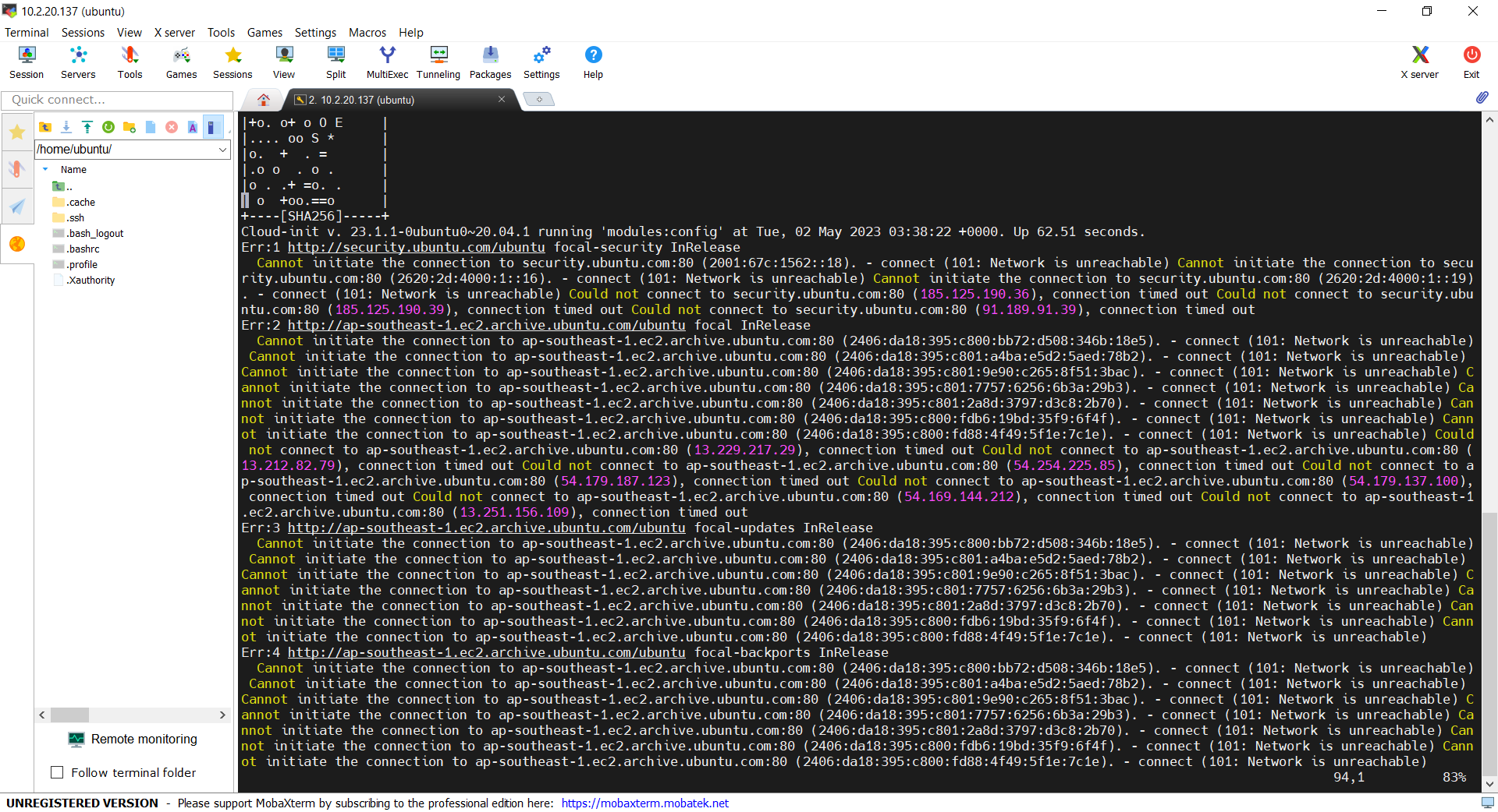
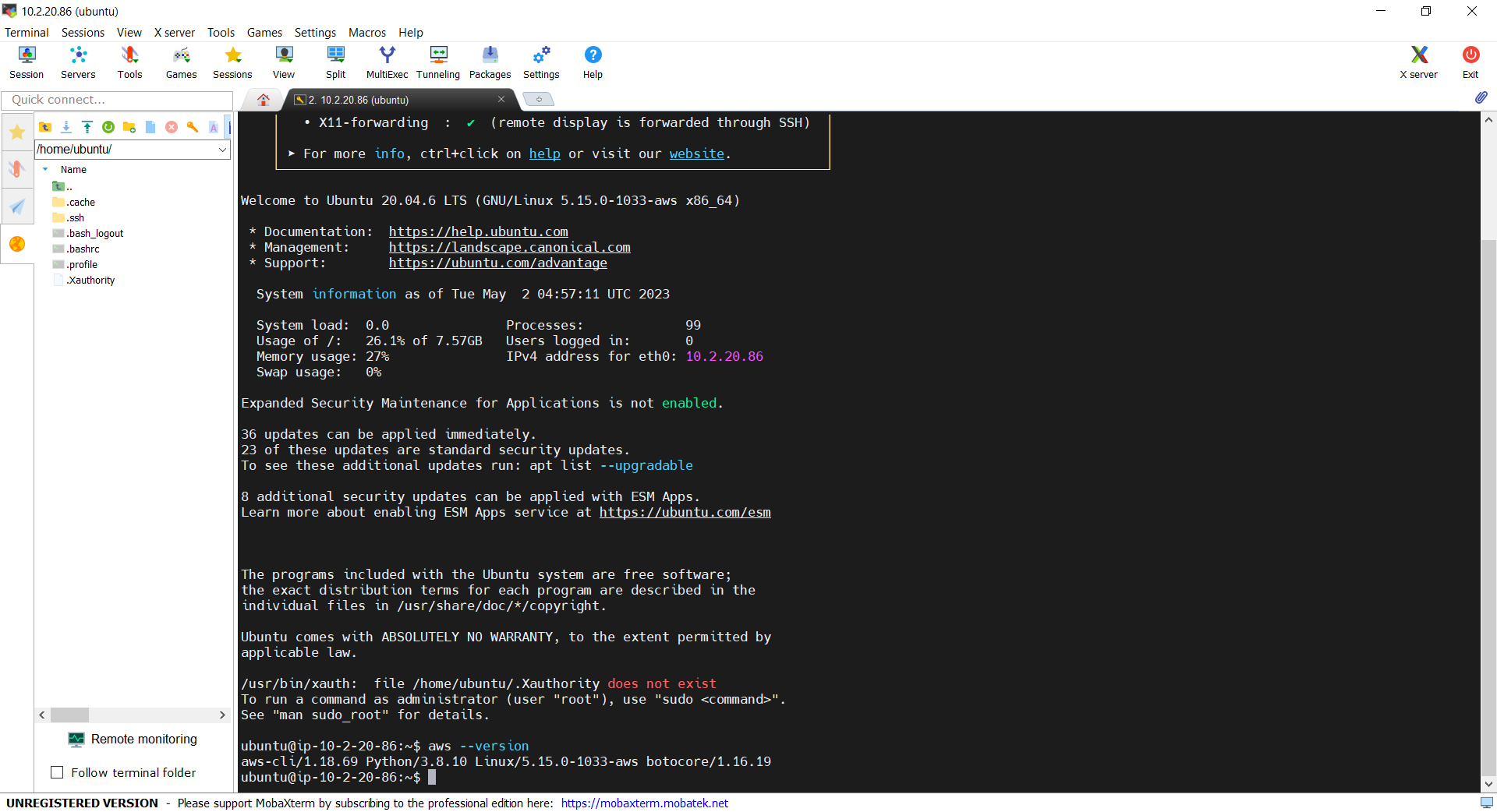
Now, let’s see if we can access the admin server via the bastion server using the private key. In fact, there is no problem to access and we can also realise that the AWS CLI is already installed properly, as shown in the screenshot below.

With the success of user_data script, we can use AWS CLI on the admin server.

Deleting the Cloud Resources

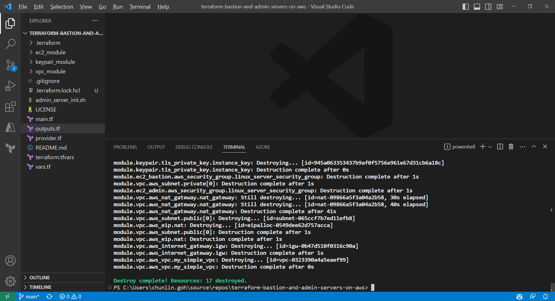
To delete what we have just setup using the Terraform code, we simply run the command terraform destroy. The complete deletion of the cloud resources is done within 3 minutes. This is definitely way more efficient than doing it manually on AWS Console.

All the 17 resources have been deleted successfully and the private key file is deleted too.

Conclusion

That is all for what I had researched on with my friend.

If you are interested, feel free to checkout our Terraform source code at https://github.com/goh-chunlin/terraform-bastion-and-admin-servers-on-aws.

Bring New Life to Old Laptop with Linux – Zorin OS Lite

According to a study conducted by the National Environment Agency (NEA) of Singapore, there are more than 60,000 tonnes of electronic waste generated in the city state a year. So, do you have an old but functioning computer and not sure what to do with it? Well, instead of throwing it away or sending it for recycling, why not re-purpose it and make it great again with lightweight OS?

Personally, for devices such as computer, even though it might not work anymore for a specific purpose, but as long as it can still function, I try to find a use for it.

NEA encourages residents to recycle the electronic waste.

I bought my first laptop in 2007 when I enrolled in the National University of Singapore. It is an Acer TravelMate 6292 with Intel Core 2 Duo T7300 CPU and 2GB RAM. The operating system installed in the machine was Windows Vista and it ran very slow. Nevertheless, I still managed to live with it and successfully completed all the assignments and projects using the slow computer.

Acer TravelMate 6292 with Windows Vista installed is the only machine I had in my 4-year campus life.

Hence, it’s now not a good idea to install Windows 10 on this 14-year-old laptop. Instead, I simply remove Windows and install a lightweight version of Linux, Zorin OS.

Why Zorin OS?

Zorin OS is fully graphical. It is a sexy looking Linux distro that manages to provide a good user experience – even with its lite edition. Speaking of user experience, although Zorin OS is an Ubuntu-based Linux distribution, it has a Windows-like graphical user interface. Hence, it is suitable to Windows users who are very accustomed to the way Windows works and are not interested in learning a new OS.

Zorin OS user interface looks just like Windows.

Zorin OS comes in two variants, i.e. Core and Lite. Here we will focus on Lite edition because it uses lightweight Xfce desktop and is intended to be the Linux for low-spec laptops and computers.

Zorin OS Lite system requirement. (Image Source: zorinos.com)

Once we are sure that our low-spec computers are capable of running Zorin OS Lite, we simply need to prepare a USB drive with at least 4GB of capacity for our Zorin OS Lite copy. Then we can start to download Zorin OS and then create an USB installation drive.

We can try Zorin OS before install it when we boot from the USB installation drive. (Image Source: zorinos.com)

Battery Replacement

The last time I changed the battery of my laptop is 10 years ago. In addition, recently the battery would become extremely hot until I couldn’t even grab my laptop when it was charging. Hence, it’s now time to replace the battery with a new one.

The battery is still available on Shopee!

The battery of the laptop is a GARDA31 6-Cell battery. I ordered one from Shopee with SGD 43.24. I received the battery one week later.

According to the spec of the battery, it has a battery life of 4 hours maximum and it would take 3 hours and 30 minutes to charge. In my case, I can only use the laptop to listen to an online radio on Chromium for at most 2 hours and 15 minutes after I have fully charged it. In addition, the CPU usage was only around 20% and RAM usage was around 1GB when the online radio is playing. However, for charging, currently it takes only around 2 hours to fully charge the battery.

System Booting Time

Currently, Zorin OS Lite took about 1 minute to boot. To find the exact time it takes to boot, we can use a tool known as systemd-analyze.

The systemd-analyze is a tool that we can use to find out the system last boot up statistics. With the systemd-analyze tool, we can find the information about how much time the system took to boot and also how much time each unit took to start, as shown in the following screenshot.

Startup finished within a minute.

We can further list all the running services that started at the boot time along with the time they took with the systemd-analyze blame command, as shown below.

Each loop device is a snap install.

Web Browsers

One of the major uses of this laptop is surfing the Internet.

By default, Firefox is pre-installed in Zorin OS. We can also install Chromium, an open-source web browser maintained by Google, from its Software store, as shown in the screenshot below.

Chromium web browser can be found in the Zorin OS Software store.

In October 2020, Microsoft announced the Edge preview builds for Linux. The release supports Ubuntu, Debian, Fedora, and openSUSE distributions. Hence, we simply need to download and install the .deb package directly from the Microsoft Edge Insider site.

Using Gdebi Package Manager to install the downloaded .deb package of Microsoft Edge. (Guide on using gdebi)

Besides listening to online radio, I also like to watch videos on Bilibili and YouTube. Unlike YouTube, Bilibili is more engaging because it has a real-time captioning system known as Danmu (弹幕) that displays user comments as streams of scrolling subtitles overlaid on the video playback screen. Due to the Danmu system, Bilibili videos don’t play well on Firefox but performs better on Chromium and Edge.

Bilibili video performance on Firefox vs Chromium on Zorin OS Lite.

Out of curiosity, I run the Basemark benchmark on Chromium, Firefox, and Edge. Here, Basemark Web 3.0 is used because it tests how well our system can use web apps. The benchmark includes various system and graphic tests that use the web recommendations and features. Firefox is a clear winner in this benchmark, with Edge and Chromium had problems on running some of the tests and Firefox couldn’t run the WebGL 2.0 Test.

Score of three web browsers on Zorin OS Lite.

Screen Recording

The video shown above is recorded using a Linux program known as SimpleScreenRecorder, which is user-friendly with a straightforward GUI.

SimpleScreenRecorder gives user a simple way to do a screen record on Linux.

To install the application, we simply need to execute the following commands.

sudo apt-get update 
sudo apt-get install simplescreenrecorder

After the videos were recorded, I edited them on my Windows machine which has a video editing software installed.

File Upload

To share the files from Zorin OS to my Windows machine, I decided to use Microsoft Azure Storage as a medium. On Zorin OS Software Store, we can easily find the Azure Storage Explorer and download it. After the Azure Storage Explorer is successfully installed, we can simply drag-and-drop files to Azure Storage and download them from other machines.

Downloading and installing Microsoft Azure Storage Explorer from Zorin OS Software store.

Chinese Input

Sometimes, I need to use Chinese in websites such as Bilibili. To add Chinese input method on Zorin OS, we will first need to install fcitx with the following command.

sudo apt install -y fcitx

Fcitx itself comes with many IMEs (Input Method Editors). Personally, I prefer fcitx-googlepinyin which is a Chinese IME using Google Pinyin. It can be installed with the following command.

sudo apt-get install fcitx-googlepinyin

After we have both of them installed, we then can proceed to follow the steps below to setup the Chinese input method.

  1. Settings > Language Support > Install / Remove Languages;
  2. Check “Chinese (simplified)”;
  3. Set “fcitx” as the Keyboard Input Method System in the Language Support window;
  4. Apply system-wide;
  5. Restart the machine;
  6. Choose “Fctix Configuration” from the “Zorin Start Menu”;
  7. Click the + button and uncheck “Only show current language”;
  8. Search “google pinyin” and add it;
  9. Done, now we can type Chinese in Zorin OS.
Setting languages and keyboard input method system in Zorin OS.

Drawing

I’ve also installed Pinta, a free and open-source program for drawing and image editing. The reason I choose to use Pinta is because it is designed in lieu of the Paint.NET on Windows.

Drawing diagram using Pinta.

Programming

I also use the laptop to learn programming at my own time. Hence, I choose to install one of my user-friendly IDEs, i.e. Visual Studio Code.

Currently, I have installed Jupyter Notebooks extension on the VS Code. The first project that I am working on now is to learn how to install and use packages, such as pandas, numpy, seaborn, and matplotlib to do statistical data visualisation, as shown below.

Working with Jupyter notebook in VS Code.

References

Run an Audio Server on Azure

Recently with music-streaming services like Spotify and YouTube Music getting popular, one may ask whether it’s possible to setup personal music-streaming service. The answer is yes.

There is a solution called Subsonic, which is developed by Sindre Mehus. However, Subsonic is no longer open source after 2016. Hence, we would talk about another open-source project inspired by Subsonic, i.e. Airsonic. According the the official website, the goal of Airsonic is to provide a full-featured, stable, self-hosted media server based on the Subsonic codebase that is free, open source, and community driven. So, let’s see how we can get Airsonic up and running on Azure.

Ubuntu on Microsoft Azure

Azure Virtual Machines supports running Linux and Windows. Airsonic can be installed on both Linux and Windows too. Since Linux is an open-source software server, it will be cheaper to run it on Azure than a Windows server.

Currently, Azure supports common Linux distributions including Ubuntu, CentOS, Debian, Red Hat, SUSE. Here, we would choose to use Ubuntu because it certainly has the upper hand when it comes to documentation and online help which makes finding OS-related solutions to easy. In addition, Ubuntu is updated frequently with LTS (Long Term Support) version released once every two years. Finally, if you are users of Debian-style distributions, Ubuntu will be a comfortable pick.

Ubuntu LTS and interim releases timeline. (Source: ubuntu.com)

Azure VM Size, Disk Size, and Cost

We should deploy a VM that provides the necessary performance for the workload at hand.

The B-series VMs are ideal for workloads that do not need the full performance of the CPU continuously. Hence, things like web servers, small databases, and our current project Airsonic is a suitable use case for B-series VMs. Hence, we will go for B1s which has only 1 virtual CPU and 1GiB of RAM. We don’t choose B1ls which has the smallest memory and lowest cost among Azure VM instances is because the installation of Airsonic on B1ls is found to be not successful. The lowest we can go is only B1s.

Choosing B1s as the VM size to host Airsonic.

For the OS disk type, instead of the default Premium SSD option, we will go for Standard SSD because it is not only a lower-cost SSD offering, but also more suitable for our audio application which is lightly used.

Remove Public Inbound Ports and Public IP Address

It’s not alright to have SSH port exposed to the Internet because there will be SSH attacks. Hence, we will remove the default public inbound ports. This will make all traffic from the Internet will be blocked. Later we will need to use a VPN connection instead to connect to the VM.

Remove all public inbound ports.

By default, when we create a VM on Azure Portal, there will be a public IP address given. It’s always recommended to not have public IP bound to the VM directly even there is only a single VM. Instead, we should deploy a load balancer in front of the VM and then have the VM bound to the load balancer. This will eventually make our life easier when we want to scale out our VM.

To not have any public IP address assigned to the VM, as shown in the screenshot below, we need to change the value of Public IP to “None”.

Setting Public IP to “None”.

Setup Virtual Network and VPN Gateway

When we create an Azure VM, we must create a Virtual Network (VNet) or use an existing VNet. A VNet is a virtual, isolated portion of the Azure public network. A VNet can then be further segmented into one or more subnets.

It is important to plan how our VM is intended to be accessed on the VNet before creating the actual VM.

The VNet configuration that we will be setting up for this project.

Since we have removed all the inbound public ports for the VM, we need to communicate with the VM through VPN. Hence, we currently need to have at least two subnets where one is for the VM and another one is for the VPN Gateway. We will add the subnet for VPN Gateway later. Now, we just do as follows.

Configuring VNet for our new VM.

Setup Point-to-Site (P2S) VPN Connection

There are already many tutorials available online about how to setup P2S VPN on Azure, for example the one written by Dishan Francis in Microsoft Tech Community, so I will not talk about how to setup the VPN Gateway on Azure. Instead, I’d like to highlight that P2S Connection is not configurable on Azure Portal if you are choosing the Basic type of the Azure VPN Gateway.

Once the VM deployment is successful, we can head to where the VNet it is located at. Then, we add the VPN Gateway subnet as shown in the screenshot below. As you can see, unlike the other subnets, the Gateway Subnet entry always has its name fixed to “GatewaySubnet” which we cannot modify.

Specifying the subnet address range for the VPN Gateway.

Next, we create a VPN Gateway. Since we are using the gateway for P2S, the type of VPN needs to be route-based. The gateway SKU that we chose here is the lowest cost, which is VpnGw1. Meanwhile, the Subnet field will be automatically chosen once we specify our VNet.

Creating a route-based VPN gateway.

The VPN gateway deployment process takes about 25 minutes. So while waiting for it to complete, we can proceed to create self-sign root and client certificates. Only root cert will be used in setting up the VPN Gateway here. The client certificate is used for installation on other computers which need P2S connections.

Once the VPN gateway is successfully deployed, we will then submit the root cert data to configure P2S, as shown below. In the Address pool field, I simply use 10.4.0.0/24 as the private IP address range that I want to use. VPN clients will dynamically receive an IP address from the range that we specify here.

Configuring Point-to-site. Saving of this will take about 5 minutes.

Now, we can download the corresponding VPN client to our local machine and install it. With this, we will get to see a new connection having our resource group name as its name available as one of the VPN connections on our machine.

A new VPN connection available to connect to our VM.

We can then connect to our VM using its private IP address, as shown in the screenshot below. Now, at least our VM is secured in the sense that its SSH port is not exposed to the public Internet.

We will not be connected with our VM through PuTTY SSH client if the corresponding VPN is disconnected.

Upgrade Ubuntu to 20.04 LTS

Once we have successfully connected to our VM, if we are using the Ubuntu 18.04 provided on Azure, then we will notice a message reminding us that there is a newer LTS version of Ubuntu available, which is Ubuntu 20.04, as shown in the screenshot below. Simply proceed to upgrade it.

New release of Ubuntu 20.04.2 LTS is available now.

Set VM Operating Hours

Since in cloud computing, we pay for what we use. Hence, it’s important that our VMs are only running when it’s necessary. If the VM doesn’t need to run 24-hour everyday, then we can configure its auto start and stop timings. For my case, I don’t listen to music when I am sleeping, so I will turn off the audio server between 12am to 6am.

To start and stop our VM at a scheduled time of the day, we can use the Tasks function, which is still in preview and available under Automation section of the VM. It will create two Logic Apps which will not automatically start or stop the VM.

Instead, I have to change the Logic Apps to send HTTP POST requests to start and powerOff endpoints of Azure directly, as suggested by R:\ob.ert in his post “Start/Stop Azure VMs during off-hours — The Logic App Solution”.

Changed the Logic Apps generated by the auto-power-off-VM template to send POST request to the powerOff endpoint directly.

Install Airsonic and Run as Standalone Programme

Since our VM will be automatically stopped and started everyday, it’s better to integrate Airsonic programme with Systemd so that Airsonic will be automatically run on each boot. There is a tutorial on how to set this up in the Airsonic documentation, so I will not describe the steps here. However, please remember to install Open JDK 8 too because Airsonic is based on Java to run.

Checking the airsonic.service status.

By default, Airsonic will be available at the port 8080 and it is listening on the path /airsonic. If the installation is successful, with our VPN connection connected, then we shall be able to see the following login screen in our first visit. Please immediately change the password as instructed for security purpose.

Welcome to Airsonic!

Public IP on VM Only via Load Balancer

We need to allow Airsonic music streaming over the public Internet and thus the VM needs to be accessible via public IP. However, since we have already earlier configured our VM to not have any public IP address, there needs to be a public load balancer bound to the VM. This setup gives us the flexibility to change the VM in the backend on the fly and secure the VM from Internet traffic.

Now, we can create a public load balancer, as shown in the screenshot below. The reason why Basic SKU which has no SLA is used here is because it’s free. SLA is optional to me here because this VM will be just a personal audio server.

Creating a new load balancer.

Basic SKU public IP address supports a dynamic as the default IP address assignment method. This means that a public IP address will be released from a resource when the resource is stopped (or deleted). The same resource will receive a different public IP address on start-up next time. If this is not what you expect, you can choose to use a static IP address to ensure it remains the same.

We now need to attach our VM to the backend pool of the load balancer, as shown in the following screenshot.

Attaching VM to the backend pool of the Azure Load Balancer.

After that, in order to allow Airsonic to be accessible from the public Internet, we shall set an inbound NAT (Network Address Translation) rule on the Azure Load Balancer. Here since I have only one VM, I directly set the VM as the target and setup a custom port mapping from port 80 to port 8080 (8080 is the default port used by Airsonic), as shown below.

A new inbound NAT rule has been set for the Airsonic VM.

Also, at the same time, we need to allow port 8080 in the Network Interface of the VM, as highlighted in the screenshot below.

Note: The VM airsonic-main-02 shown in the screenshot is the 2nd VM that I have for the same project. It is same as airsonic-main VM.

Allow inbound port 8080 on the Airsonic VM.

Once we have done all these, we can finally access Airsonic through the public IP address of the load balancer.

Enjoy the Music

By default, the media folder that will be used by Airsonic is at /var/music, as shown below. If this music folder does not exist yet, simply proceed to create one.

Airsonic will scan the media folder every day at 3am by default.

By default, the media folder is not accessible by any of the users. We need to explicitly give users the access to the media folders, as shown in the screenshot below.

Giving user access to the media folders.

As recommended by Airsonic, the music folders we add to /var/music and other media folders are better organized in an “artist/album/song” manner. This will help Airsonic to automatically build the albums. In addition, since I have already entered the relevant properties such as title and artist name to the music files, so Airsonic can read them and display on the web app, as shown in the screenshot below.

The cover image is automatically picked up from an image file named cover.png in the corresponding album folder.

In addition, both Airsonic and Subsonic provide the same API. Hence, we can access our music on Airsonic through Subsonic mobile apps as well. Currently I am using the free app Subsonic Music Streamer on my Android phone and it works pretty well.

The music on our Airsonic server can be accessed through Subsonic mobile app too!

References

Personal OneDrive Music Player on Raspberry Pi with a Web-based Remote Control (Part 1)

There are so much things that we can build with a Raspberry Pi. It’s always my small little dream to have a personal music player that sits on my desk. With the successful setup of the Raspberry Pi 3 Model B few weeks ago, it’s time to realise that dream.

Project GitHub Repository

The complete source code of the music player program on the Raspberry Pi mentioned in this article can be found at https://github.com/goh-chunlin/Lunar.Music.RaspberryPi.

Project Objective

In this article and the next, I will be sharing with you the journey of building a personal music player on Raspberry Pi. The end product will just be like Spotify on Google Nest Hub where we can listen to our favourite music not on our computer or smart phone but on another standalone device, which is Raspberry Pi in this case.

In this project, there is no monitor or any other displays connected to my Raspberry Pi. So the output is simply music and songs. However, since there is no touch screen for user to interact with the Raspberry Pi like how Google Nest Hub does, we will need to use a web app which acts as the remote control of the Raspberry Pi music player. With the web app, user will be able to scan through the playlist and choose which music or song to play.

A month in, I barely use the Google Nest Hub Max (yet I still recommend it)
[Image Caption: Spotify on Google Nest Hub (Image Credit: Android Authority)]

In addition, while Google Nest Hub has its music streamed from Spotify, the music that our Raspberry Pi music player will use is available on our personal OneDrive Music folder. In the next article, I will talk more about how we can use Azure Active Directory and Microsoft Graph API to connect with our personal OneDrive service.

So with this introduction, we can confirm that the objective of this project is to build a music player on a Raspberry Pi which can be controlled remotely via a web app to play music from OneDrive.

[Image Caption: System design of this music player together with its web portal.]

We will only focus on the setup of Raspberry Pi and RabbitMQ server in this Part 1 of the article. In the Part 2, which can be found by clicking here, we will continue to talk about the web portal and how we access the OneDrive with Microsoft Graph and go-onedrive client.

Installing Golang on Raspberry Pi

The music player that we are going to build is using Golang. The reason of choosing Golang is because it’s easy to work with, especially integrating with the RabbitMQ server.

To install Golang on a Raspberry Pi, we can simply use the following command.

$ sudo apt-get install golang

However, please take note that the version of the Golang downloaded is not the latest one. So the alternative way of doing it is download the package from the Golang official website with the following commands.

Since the Raspberry Pi 3 Model B is having a 64-bit ARMv8 CPU and the latest Golang version is 1.15.5, according to the Golang website, what we need to download is the highlighted one in the following screenshot. Hence, we can run the following commands.

$ wget https://golang.org/dl/go1.15.5.linux-arm64.tar.gz
$ sudo tar -C /usr/local -xzf go1.15.5.linux-arm64.tar.gz
$ rm go1.15.5.linux-arm64.tar.gz
[Image Caption: Finding the correct package to download for Raspberry Pi 3 Model B.]

Now we have Golang installed on our Raspberry Pi, we can proceed to build the music player.

Music Player on Raspberry Pi

The multimedia player used in this project is the VLC Media Player which is not only free and open-source but also cross-platform. The reason VLC Media Player is chosen is also because it has nvlc, a command-line ncurses interface to play an MP3. Hence, to play an MP3 with nvlc, we just need to run the following command.

$ nvlc <mp3_file> --play-and-exit

The –play-and-exit flag is added to make sure that the VLC will exit once the particular music is finished.

Also, we can use Go exec command to execute the command above. For example, if we have an MP3 file called song and it’s stored in the directory songFileRoot, then we can play the MP3 file with the following codes.

cmd := exec.Command("nvlc", song, "--play-and-exit")

cmd.Dir = songFileRoot
cmd.Stdout = os.Stdout
cmd.Stderr = os.Stdout

if err := cmd.Run(); err != nil {
    fmt.Println("Error:", err)
}

Messaging, RabbitMQ, and Remote Controlling Via Web App

Now we need a communication channel for our web app to tell the Golang programme above which MP3 file to play.

A common way is to use HTTP and REST to communicate. That will require us to design some RESTful HTTP APIs and turn our Raspberry Pi to be a web server so that the web app can invoke the APIs with HTTP request.

Using RESTful API sounds great and easy but what if the Raspberry Pi is not responding? Then our web app has to implement some sort of reconnection or failover logic. In addition, when our web app makes a call to the API, it will be blocked waiting for a response. Finally, due to the nature of RESTful API, there will always be some coupling of services.

This makes me turn to an alternative way, which is messaging which is loose coupling and asynchronous. Using messaging with message brokers like RabbitMQ helps a lot with scalability too.

Here RabbitMQ is used because is a popular light-weight message broker and it’s suitable for general-purpose messaging. Also, I like how RabbitMQ simply stores messages and passes them to consumers when ready.

It’s also simple to setup RabbitMQ on a cloud server too. For example, now on Microsoft Azure, we can just launch a VM running Ubuntu 18.04 LTS and follow the steps listed in the tutorials below to install RabbitMQ Server on Azure.

RabbitMQ supports several messaging protocols, directly and through the use of plugins. Here we will be using the AMQP 0-9-1 which we have Golang client support for it as well.

How about the message format? Basically, to RabbitMQ, all messages are just byte arrays. So, we can store our data in JSON and serialise the JSON object to byte array before sending the data via RabbitMQ. Hence, we have the two structs below.

type Command struct {
    Tasks []*Task `json:"tasks"`
}

type Task struct {
    Name    string   `json:"name"`
    Content []string `json:"content"`
}

With this, we then can publish the message via RabbitMQ as follows.

ch, err := conn.Channel()
...
err = ch.Publish(
    "",     // exchange
    q.Name, // routing key
    false,  // mandatory
    false,  // immediate
    amqp.Publishing{
        ContentType: "application/json",
        Body:        body,
    }
)

When the message is received at Raspberry Pi side, we simply need to de-serialise it accordingly to get the actual data.

Now, by connecting both the Raspberry Pi music player and the web app to the RabbitMQ server, both of them can communicate. We will then make our app web app as a sender to send the music filename over to the music player on the Raspberry Pi to instruct it to play the music.

Transferring OneDrive Music to Raspberry Pi

The music is stored on personal OneDrive Music folder online. Hence, it’s not a wise idea to always let our Raspberry Pi to stream the music from OneDrive every time the same music is chosen. Instead, we shall download only once to the Raspberry Pi right before the first time of a music is playing.

Hence, in our music player programme, we have a data file called playlist.data which keeps track of the OneDrive Item ID and its local file name on the Raspberry Pi. Once the music is successfully downloaded to the Raspberry Pi, a new line of record as shown below will be appended to the data file.

121235678##########music.mp3

Hence for the subsequent play of the same music, the music player programme will scan through the data file and play the local MP3 file instead of downloading it again from OneDrive.

func isDriveItemDownloaded(driveItemId string) bool {
    isMusicFileDownloaded := false

    dataFile, err := os.Open("playlist.dat")

    defer dataFile.Close()

    if err == nil {
        scanner := bufio.NewScanner(dataFile)
        scanner.Split(bufio.ScanLines)

        for scanner.Scan() {
            line := scanner.Text()
            if !isMusicFileDownloaded && 0 == strings.Index(line, driveItemId) {
                lineComponents := strings.Split(line, "##########")
                playSingleMusicFile(lineComponents[1])
                isMusicFileDownloaded = true
            }
        }
    }
    return isMusicFileDownloaded
}

Launch the Music Player Automatically

With our music player ready, instead of having us to launch it manually, could we make it run on our Raspberry Pi at startup? Yes, there are five ways of doing so listed on the Dexter Industry article. I choose to modify the .bashrc file which will run the music player when we boot up the Raspberry Pi and log in to it.

$ sudo nano /home/pi/.bashrc

In the .bashrc file, we simply need to append the following lines where we will change directory to the root of the music player programme. We cannot simply just run the programme just yet. We need to make sure two things.

Firstly, we need to make our music player run in the background. Doing so is because we want to continue to use the shell without waiting for the song finishes playing. So we can simply add the & to the end of the command so that the music player programme will start in the background.

Secondly, since we login to the Raspberry Pi using SSH, when we start a shell script and then logout from it, the process will be killed and thus cause the music player programme to stop. Hence, we need nohup (no hang up) command to catch the hangup signal so that our programme can run even after we log out from the shell.

# auto run customised programmes
cd /home/pi/golang/src/music-player
nohup ./music-player &

USB Speaker and ALSA

Next, we need to connect our Raspberry Pi to a speaker.

I get myself a USB speaker from Sim Lim Square which uses a “C-Media” chipset.. Now, I simply need to connect it to the Raspberry Pi.

[Image Caption: C-Media Electronics Inc. is a Taiwan computer hardware company building processors for audio devices.]

Next, we can use lsusb, as shown below, to display information about USB buses in Raspberry Pi and the devices connected to them. We should be able to locate the speaker that we just connect.

$ lsusb
Bus 001 Device 004: ID ... C-Media Electronics, Inc. Audio Adapter
Bus 001 Device 003: ID ...
...

Hence now we know that the USB speaker is successfully picked up by the Raspberry Pi OS.

We can then proceed to list down all soundcards and digital audio devices with the following command.

$ aplay -l
**** List of PLAYBACK Hardware devices ****
card 0: Headphones...
  Subdevices: 8/8
  Subdevices #0: ...
  ...
card 1: Set [C-Media USB Headphone Set], device 0: USB Audio [USB Audio]
  ...

Now we also know that the USB speaker is at the Card 1. With this info, we can set the USB speaker as the default audio device by editing the configuration file of ALSA, the Advanced Linux Sound Architecture. ALSA is used for providing kernel driven sound card drivers.

$ sudo nano /usr/share/alsa/alsa.conf

The following two lines in the file are the only lines we need to update to be as follows in the file. The reason we put “1” for both of them because the USB speaker is using card 1, as shown above. So the number may be different for your device. For more information about this change, please refer to the ALSA Project page about setting default device.

defaults.ctl.card 1
defaults.pcm.card 1

Finally, if you would like to adjust the volume of the speaker, you can use alsamixer. Alsamixer is an ncurses mixer program for use with ALSA soundcard drivers.

$ alsamixer

There is a very good article about setting up USB speaker on Raspberry Pi by Matt on raspberrypi-spy.co.uk website. Feel free to refer to it if you would like to find our more.

Next: The Web-Based Remote Control and OneDrive

Since now we’ve already successfully setup the music player on the Raspberry Pi, it’s time to move on to see how we can control it from a website and how we can access our personal OneDrive Music folder with Azure AD and Microsoft Graph.

When you’re ready, let’s continue our journey here: https://cuteprogramming.wordpress.com/2020/11/21/personal-onedrive-music-player-on-raspberry-pi-with-a-web-based-remote-control-part-2/.

References

The code of the music player described in this article can be found in my GitHub repository: https://github.com/goh-chunlin/Lunar.Music.RaspberryPi.