For .NET developers looking for Content Management System (CMS) solution, Orchard Core presents a compelling, open-source option. Orchard Core is a CMS built on ASP.NET Core. When deploying Orchard Core on AWS, the Elastic Container Service (ECS) provides a good hosting platform that can handle high traffic, keep costs down, and remain stable.
However, finding clear instructions for deploying Orchard Core to ECS end-to-end can be difficult. This may require us to do more testing and troubleshooting, and potentially lead to a less efficient or secure setup. A lack of a standard deployment process can also complicate infrastructure management and hinder the implementation of CI/CD. This is where Infrastructure as Code (IaC) comes in.
Source Code
The complete CloudFormation template we built in this article is available on GitHub: https://github.com/gcl-team/Experiment.OrchardCore.Main/blob/main/Infrastructure.yml
CloudFormation
IaC provides a solution for automating infrastructure management. With IaC, we define our entire infrastructure which hosts Orchard Core setup as code. This code can then be version-controlled, tested, and deployed just like application code.
CloudFormation is an AWS service that implements IaC. By using CloudFormation, AWS automatically provisions and configures all the necessary resources for our Orchard Core hosting, ensuring consistent and repeatable deployments across different environments.
This article is for .NET developers who know a bit about AWS concepts such as ECS or CloudFormation. We’ll demonstrate how CloudFormation can help to setup the infrastructure for hosting Orchard Core on AWS.

Now let’s start writing our CloudFormation as follows. We start by defining some useful parameters that we will be using later. Some of the parameters will be discussed in the following relevant sections.
AWSTemplateFormatVersion: '2010-09-09'
Description: "Infrastructure for Orchard Core CMS"

Parameters:
  VpcCIDR:
    Type: String
    Description: "VPC CIDR Block"
    Default: 10.0.0.0/16
    AllowedPattern: '((\d{1,3})\.){3}\d{1,3}/\d{1,2}'
  ApiGatewayStageName:
    Type: String
    Default: "production"
    AllowedValues:
      - production
      - staging
      - development
  ServiceName:
    Type: String
    Default: cld-orchard-core
    Description: "The service name"
  CmsDBName:
    Type: String
    Default: orchardcorecmsdb
    Description: "The name of the database to create"
  CmsDbMasterUsername:
    Type: String
    Default: orchardcoreroot
  HostedZoneId:
    Type: String
    Default: <your Route 53 hosted zone id>
  HostedZoneName:
    Type: String
    Default: <your custom domain>
  CmsHostname:
    Type: String
    Default: orchardcms
  OrchardCoreImage:
    Type: String
    Default: <your ECR link>/orchard-core-cms:latest
  EcsAmi:
    Description: The Amazon Machine Image ID used for the cluster
    Type: AWS::SSM::Parameter::Value<AWS::EC2::Image::Id>
    Default: /aws/service/ecs/optimized-ami/amazon-linux-2023/recommended/image_id
Dockerfile
The Dockerfile is quite straightforward.
# Global Arguments
ARG DCR_URL=mcr.microsoft.com
ARG BUILD_IMAGE=${DCR_URL}/dotnet/sdk:8.0-alpine
ARG RUNTIME_IMAGE=${DCR_URL}/dotnet/aspnet:8.0-alpine

# Build Container
FROM ${BUILD_IMAGE} AS builder
WORKDIR /app

COPY . .

RUN dotnet restore
RUN dotnet publish ./OCBC.HeadlessCMS/OCBC.HeadlessCMS.csproj -c Release -o /app/src/out

# Runtime Container
FROM ${RUNTIME_IMAGE}

## Install cultures
RUN apk add --no-cache \
   icu-data-full \
   icu-libs

ENV ASPNETCORE_URLS http://*:5000

WORKDIR /app

COPY --from=builder /app/src/out .

EXPOSE 5000

ENTRYPOINT ["dotnet", "OCBC.HeadlessCMS.dll"]
With the Dockerfile, we then can build the Orchard Core project locally with the command below.
docker build --platform=linux/amd64 -t orchard-core-cms:v1 .
The --platform flag specifies the target OS and architecture for the image being built. Even though it is optional, it is particularly useful when building images on a different platform (like macOS or Windows) and deploying them to another platform (like Amazon Linux) that has a different architecture.

I am using macOS with ARM-based Apple Silicon, whereas Amazon Linux AMI uses amd64 (x86_64) architecture. Hence, if I do not specify the platform, the image I build on my Macbook will be incompatible with EC2 instance.
Once the image is built, we will push it to the Elastic Container Registry (ECR).
We choose ECR because it is directly integrated with ECS, which means deploying images from ECR to ECS is smooth. When ECS needs to pull an image from ECR, it automatically uses the IAM role to authenticate and authorise the request to ECR. The execution role of our ECS is associated with the AmazonECSTaskExecutionRolePolicy IAM policy, which allows ECS to pull images from ECR.
ECR also comes with built-in support for image scanning, which automatically scans our images for vulnerabilities.

Unit 01: IAM Role
Technically, we are able to run Orchard Core on ECS without any ECS task role. However, that is possible only if our Orchard Core app does not need to interact with AWS services. Not only for our app, but actually most of the modern web apps, we always need to integrate our app with AWS services such as S3, CloudWatch, etc. Hence, the first thing that we need to work on is setting up an ECS task role.
iamRole:
  Type: AWS::IAM::Role
  Properties:
    RoleName: !Sub "${AWS::StackName}-ecs"
    Path: !Sub "/${AWS::StackName}/"
    AssumeRolePolicyDocument:
      Version: 2012-10-17
      Statement:
        - Effect: Allow
          Principal:
            Service:
              - ecs-tasks.amazonaws.com
          Action:
            - sts:AssumeRole
In AWS IAM, permissions are assigned to roles, not directly to the services that need them. Thus, we cannot directly assign IAM policies to ECS tasks. Instead, we assign those policies to a role, and then the ECS task temporarily assumes that role to gain those permissions, as shown in the configuration above.
Roles are considered temporary because they are only assumed for the duration that the ECS task needs to interact with AWS resources. Once the ECS task stops, the temporary permissions are no longer valid, and the service loses access to the resources.
Hence, by using roles and AssumeRole, we follow the principle of least privilege. The ECS task is granted only the permissions it needs and can only use them temporarily.
Unit 02: CloudWatch Log Group
ECS tasks, by default, do not have logging enabled.
Hence, assigning a role to our ECS task for logging to CloudWatch Logs is definitely one of the first roles we should assign when setting up ECS tasks. Setting logging up early helps to avoid surprises later on when our ECS tasks are running.
To setup the logging, we first need to specify Log Group, a place in CloudWatch that logs go. While ECS itself can create the log group automatically when the ECS task starts (if it does not already exist), it is a good practice to define the log group in CloudFormation to ensure it exists ahead of time and can be managed within our IaC.
ecsLogGroup:
  Type: AWS::Logs::LogGroup
  Properties:
    LogGroupName: !Sub "/ecs/${ServiceName}-log-group"
    RetentionInDays: 3
    Tags:
      - Key: Stack
        Value: !Ref AWS::StackName
The following policy will grant the necessary permissions to write logs to CloudWatch.
ecsLoggingPolicy:
  Type: AWS::IAM::Policy
  Properties:
    PolicyName: !Sub "${AWS::StackName}-cloudwatch-logs-policy"
    Roles:
      - !Ref iamRole
    PolicyDocument:
      Version: 2012-10-17
      Statement:
        - Effect: Allow
          Action:
            - logs:CreateLogStream
            - logs:PutLogEvents
          Resource:
            - !Sub "arn:aws:logs:${AWS::Region}:${AWS::AccountId}:log-group:/ecs/${ServiceName}-log-group/*"
By separating the logging policy into its own resource, we make it easier to manage and update policies independently of the ECS task role. After defining the policy, we attach it to the ECS task role by referencing it in the Roles section.

Unit 03: S3 Bucket
We will be storing the files uploaded to the Orchard Core through its Media module on Amazon S3. So, we need to configure our S3 Bucket as follows.
mediaContentBucket:
  Type: AWS::S3::Bucket
  Properties:
    BucketName: !Join
      - '-'
      - - !Ref ServiceName
        - !Ref AWS::Region
        - !Ref AWS::AccountId
    OwnershipControls:
      Rules:
        - ObjectOwnership: BucketOwnerPreferred
    Tags:
      - Key: Stack
        Value: !Ref AWS::StackName
Since bucket names must be globally unique, we dynamically create it using AWS Region and AWS Account ID.
Since our Orchard Core can be running in multiple ECS tasks that upload media files to a shared S3 bucket, the BucketOwnerPreferred setting ensures that even if media files are uploaded by different ECS tasks, the owner of the S3 bucket can still access, delete, or modify any of those media files without needing additional permissions for each uploaded object.
The bucket owner having full control is a security necessity in many cases because it allows the owner to apply policies, access controls, and auditing in a centralised way, maintaining the security posture of the bucket.
However, even if the bucket owner has control, the principle of least privilege should still apply. For example, only the ECS task responsible for Orchard Core should be allowed to interact with the media objects.
mediaContentBucketPolicy:
  Type: AWS::IAM::Policy
  Properties:
    PolicyName: !Sub "${mediaContentBucket}-s3-policy"
    Roles:
      - !Ref iamRole
    PolicyDocument:
      Version: 2012-10-17
      Statement:
        - Effect: Allow
          Action:
            - s3:ListBucket
          Resource: !GetAtt mediaContentBucket.Arn
        - Effect: Allow
          Action:
            - s3:PutObject
            - s3:GetObject
          Resource: !Join ["/", [!GetAtt mediaContentBucket.Arn, "*"]]
Keeping the s3:ListBucket permission in the policy is a necessary permission for Orchard Core Media module to work properly. Meanwhile, both s3:PutObject and s3:GetObject are used for uploading and downloading media files.
IAM Policy
Now, let’s pause a while to talk about the policies that we have added above for the log group and S3.
In AWS, we mostly deal with managed policies and inline policies depending on whether the policy needs to be reused or tightly scoped to one role.
We use AWS::IAM::ManagedPolicy when the permission needs to be reused by multiple roles or services. So it is frequently used in company-wide security policies. Thus it is not suitable for our Orchard Core examples above. Instead, we use AWS::IAM::Policy because it is for a permission which is tightly connected to a single role and will not be reused elsewhere.
In addition, since AWS::IAM::Policy is tightly tied to entities, it will be deleted when the corresponding entities are deleted. This is a key difference from AWS::IAM::ManagedPolicy, which remains even if the entities that use it are deleted. This explains why managed policy is used in company-wide policies because managed policy provides better long-term management for permissions that may be reused across multiple roles.
We can summarise the differences between two of them into the following table.
| Feature | Managed Policy | Policy |
| Scope | Company-wide. | Tight coupling to a single entity. |
| Deletion Behaviour | Persists even if attached entities are deleted. | Deleted along with the associated entity. |
| Versioning Support | Supports versioning (can roll back). | No. |
| Limit per Entity | 20. | 10. |
| Best Use Case | Long-term, reusable permissions (e.g., company-wide security policies). | One-off, tightly scoped permissions (e.g., role-specific needs). |
Unit 04: Aurora Database Cluster
Orchard Core supports Relational DataBase Management System (RDBMS). Unlike traditional CMS platforms that rely on a single database engine, Orchard Core offers flexibility by supporting multiple RDBMS options, including:
- Microsoft SQL Server;
- PostgreSQL;
- MySQL;
- SQLite.
While SQLite is lightweight and easy to use, it is not suitable for production deployments on AWS. SQLite is designed for local storage, not multi-user concurrent access. On AWS, there are fully managed relational databases (RDS and Aurora) provided instead.

While Amazon RDS is a well-known choice for relational databases, we can also consider Amazon Aurora, which was launched in 2014. Unlike traditional RDS, Aurora automatically scales up and down, reducing costs by ensuring we only pay for what we use.

In addition, Aurora is faster than standard PostgreSQL and MySQL, as shown in the screenshot above. It also offers built-in high availability with Multi-AZ replication. This is critical for a CMS like Orchard Core, which relies on fast queries and efficient data handling.
It is important to note that, while Aurora is optimised for AWS, it does not lock us in, as we retain full control over our data and schema. Hence, if we ever need to switch, we can export data and move to standard MySQL/PostgreSQL on another cloud or on-premises.
Instead of manually setting up Aurora, we will be using CloudFormation to ensure that the correct database instance, networking, security settings, and additional configurations are managed consistently.
Aurora is cluster-based rather than standalone DB instances like traditional RDS. Thus, instead of a single instance, we deploy a DB cluster, which consists of a primary writer node and multiple reader nodes for scalability and high availability.
Because of this cluster-based architecture, Aurora does not use the usual DBParameterGroup like standalone RDS instances. Instead, it requires a DBClusterParameterGroup to apply settings at the cluster level, ensuring all instances in the cluster inherit the same configuration, as shown in the following Cloudformation template.
cmsDBClusterParameterGroup:
  Type: AWS::RDS::DBClusterParameterGroup
  Properties:
    Description: "Aurora Provisioned Postgres DB Cluster Parameter Group"
    Family: aurora-postgresql16
    Parameters:
      timezone: UTC  # Ensures consistent timestamps
      rds.force_ssl: 1  # Enforce SSL for security
The first parameter we configure is the timezone. We set it to UTC to ensure consistency. So when we store date-time values in the database, we should use TIMESTAMPTZ for timestamps, and store the time zone as a TEXT field. After that, when we need to display the time in a local format, we can use the AT TIME ZONE feature in PostgreSQL to convert from UTC to the desired local time zone. This is important because PostgreSQL returns all times in UTC, so storing the time zone ensures we can always retrieve and present the correct local time when needed, as shown in the query below.
SELECT event_time_utc AT TIME ZONE timezone AS event_local_time
FROM events;
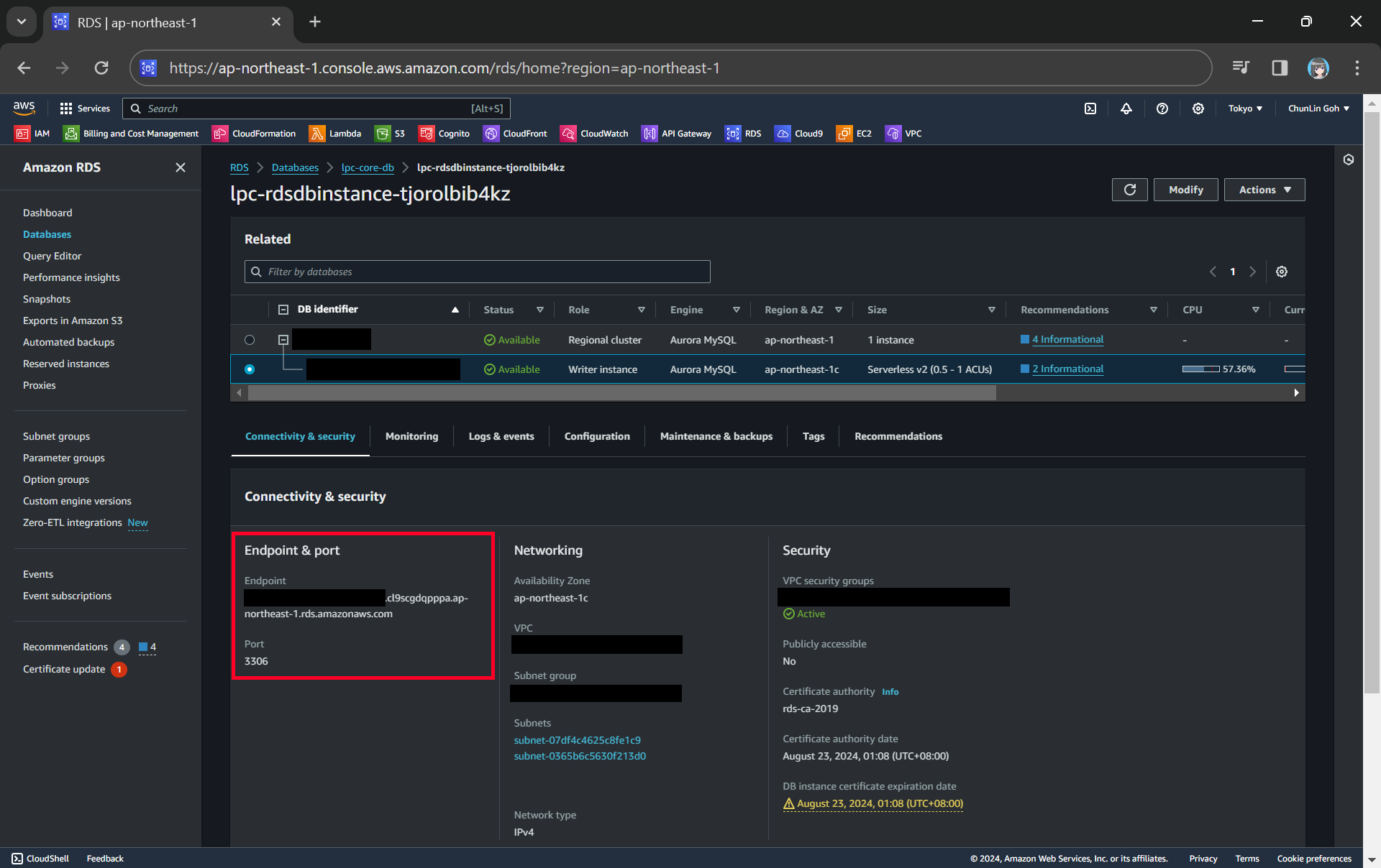
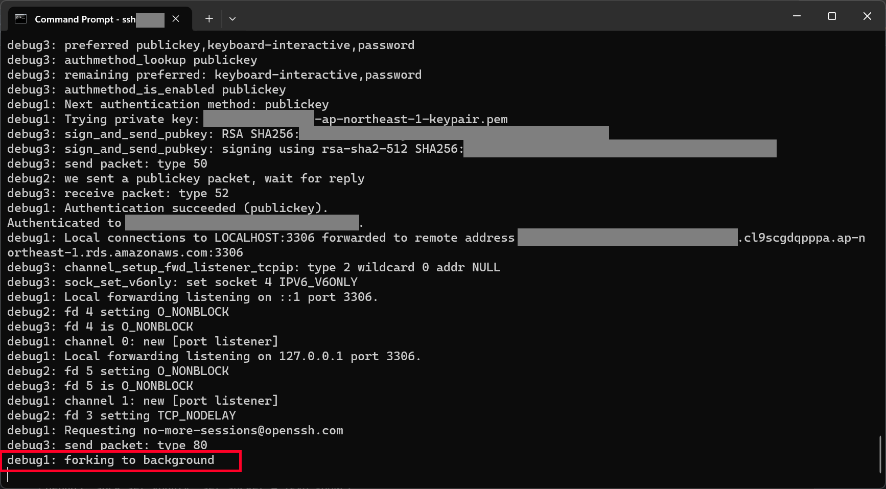
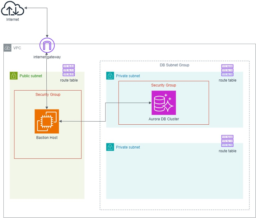
After that, we enabled the rds.force_ssl so that all connections to our Aurora are encrypted using SSL. This is necessary to prevent data from being sent in plaintext. Even if our Aurora database is behind a bastion host, enforcing SSL connections is still recommended because SSL ensures the encryption of all data in transit, adding an extra layer of security. It is also worth mentioning that enabling SSL does not negatively impact performance much, but it adds a significant security benefit.
Once the DBClusterParameterGroup is configured, the next step is to configure the AWS::RDS::DBCluster resource, where we will define the cluster main configuration with the parameter group defined above.
cmsDatabaseCluster:
  Type: AWS::RDS::DBCluster
  Properties:
    BackupRetentionPeriod: 7
    DatabaseName: !Ref CmsDBName
    DBClusterIdentifier: !Ref AWS::StackName
    DBClusterParameterGroupName: !Ref cmsDBClusterParameterGroup
    DeletionProtection: true
    Engine: aurora-postgresql
    EngineMode: provisioned
    EngineVersion: 16.1
    MasterUsername: !Ref CmsDbMasterUsername
    MasterUserPassword: !Sub "{{resolve:ssm-secure:/OrchardCoreCms/DbPassword:1}}"
    DBSubnetGroupName: !Ref cmsDBSubnetGroup
    VpcSecurityGroupIds:
      - !GetAtt cmsDBSecurityGroup.GroupId
    Tags:
      - Key: Stack
        Value: !Ref AWS::StackName
Let’s go through the Properties.
About BackupRetentionPeriod
The BackupRetentionPeriod parameter in the Aurora DB cluster determines how many days automated backups are retained by AWS. It can be from a minimum of 1 day to a maximum of 35 days for Aurora databases. For most business applications, 7 days of backups is often enough to handle common recovery scenarios unless we are required by law or regulation to keep backups for a certain period.
Aurora automatically performs incremental backups for our database every day, which means that it does not back up the entire database each time. Instead, it only stores the changes since the previous backup. This makes the backup process very efficient, especially for databases with little or no changes over time. If our CMS database remains relatively static, then the backup storage cost will remain very low or even free as long as our total backup data for the whole retention period does not exceed the storage capacity of our database.
So the total billed usage for backup depends on how much data is being changed each day, and whether the total backup size exceeds the volume size. If our database does not experience massive daily changes, the backup storage will likely remain within the database size and be free.
About DBClusterIdentifier
For the DBClusterIdentifier, we set it to the stack name, which makes it unique to the specific CloudFormation stack. This can be useful for differentiating clusters.
About DeletionProtection
In production environments, data loss or downtime is critical. DeletionProtection ensures that our CMS DB cluster will not be deleted unless it is explicitly disabled. There is no “shortcut” to bypass it for production resources. If DeletionProtection is enabled on the DB cluster, even CloudFormation will fail to delete the DB cluster. The only way to delete the DB cluster is that we disable DeletionProtection first via the AWS Console, CLI or SDK.
About EngineMode
In Aurora, EngineMode refers to the database operational mode. There are two primary modes, i.e. Provisioned and Serverless. For Orchard Core, Provisioned mode is typically the better choice because the mode ensures high availability, automatic recovery, and read scaling. Hence, if the CMS is going to have a consistent level of traffic, Provisioned mode will be able to handle that load. Serverless is useful if our CMS workload has unpredictable traffic patterns or usage spikes.
About MasterUserPassword
Storing database passwords directly in the CloudFormation template is a security risk.
There are a few other ways to handle sensitive data like passwords in CloudFormation, for example using AWS Secrets Manager and AWS Systems Manager (SSM) Parameter Store.
AWS Secrets Manager is a more advanced solution that offers automatic password rotation, which is useful for situations where we need to regularly rotate credentials. However, it may incur additional costs.
On the other hand, SSM Parameter Store provides a simpler and cost-effective solution for securely storing and referencing secrets, including database passwords. We can store up to 10,000 parameters (standard type) without any cost.
Hence, we need to use SSM Parameter Store to securely store the database password and reference it in CloudFormation without exposing it directly in our template, reducing the security risks and providing an easier management path for our secrets.


About DBSubnetGroupName and VpcSecurityGroupIds
These two configurations about Subnet and VPC will involve networking considerations. We will discuss further when we dive into the networking setup later.
Unit 05: Aurora Database Instance
Now that we have covered the Aurora DB cluster, which is the overall container for the database, let’s move on to the DB instance.
Think of the cluster as the foundation, and the DB instances are where the actual database operations take place. The DB instances are the ones that handle the read and write operations, replication, and scaling for the workload. So, in order for our CMS to work correctly, we need to define the DB instance configuration, which runs on top of the DB cluster.
cmsDBInstance:
  Type: 'AWS::RDS::DBInstance'
  DeletionPolicy: Retain
  Properties:
    DBInstanceIdentifier: !Sub "${AWS::StackName}-db-instance"
    DBInstanceClass: db.t4g.medium
    DBClusterIdentifier: !Ref cmsDatabaseCluster
    DBSubnetGroupName: !Ref cmsDBSubnetGroup
    Engine: aurora-postgresql
    Tags:
      - Key: Stack
        Value: !Ref AWS::StackName
For our Orchard Core CMS, we do not expect very high traffic or intensive database operations. Hence, we choose to use db.t4g. T4g database instances are AWS Graviton2-based, thus they are more cost-efficient than traditional instance types, especially for workloads like a CMS that does not require continuous high performance. However, there are a few things we make need to look into when using T instance classes.
Unit 06: Virtual Private Cloud (VPC)
Now that we have covered how the Aurora cluster and instance work, the next important thing is ensuring they are deployed in a secure and well-structured network. This is where the Virtual Private Cloud (VPC) comes in.
VPC is a virtual network in AWS where we define the infrastructure networking. It is like a private network inside AWS where we can control IP ranges, subnets, routing, and security.

By the way, you might have noticed that AWS automatically provides a default VPC in every region. It is a ready-to-use network setup that allows us to launch resources without configuring networking manually.
While it is convenient, it is recommended not to use the default VPC. This is because the default VPC is automatically created with predefined settings, which means we do not have full control over its configuration, such as subnet sizes, routing, security groups, etc. It also has public subnets by default which can accidentally expose internal resources to the Internet.
Since we are setting up our own VPC, one key decision we need to make is the CIDR block, i.e. the range of private IPs we allocate to our network. This is important because it determines how many subnets and IP addresses we can have within our VPC.
To future-proof our infrastructure, we will be using a /16 CIDR block, as shown in the VpcCIDR in our CloudFormation template. This gives us 65,536 IP addresses, which we can break into 64 subnets of /22 (each having 1,024 IPs). 64 subnets is usually more than enough for a well-structured VPC because most companies do not even need so many subnets in a single VPC unless they have very complex workloads. Just in case if one service needs more IPs, we can allocate a larger subnet, for example /21 instead of /22.
In the VPC setup, we are also trying to avoid creating too many VPCs unnecessarily. Managing multiple VPCs means handling VPC peering which increases operational overhead.
vpc:
  Type: AWS::EC2::VPC
  Properties:
    CidrBlock: !Ref VpcCIDR
    InstanceTenancy: default
    EnableDnsSupport: true
    EnableDnsHostnames: true
    Tags:
      - Key: Name
        Value: !Sub "${AWS::AccountId}-${AWS::Region}-vpc"
Since our ECS workloads and Orchard Core CMS are public-facing, we need EnableDnsHostnames: true so that public-facing instances get a public DNS name. We also need EnableDnsSupport: true to allow ECS tasks, internal services, and AWS resources like S3 and Aurora to resolve domain names internally.
For InstanceTenancy, which determines whether instances in our VPC run on shared (default) or dedicated hardware, it is recommended to use the default because AWS automatically places instances on shared hardware, which is cost-effective and scalable. We only need to change it if we are asked to use dedicated instances with full hardware isolation.
Now that we have defined our VPC, the next step is planning its subnet structure. We need both public and private subnets for our workloads.
Unit 07: Subnets and Subnet Groups
For our VPC with a /16 CIDR block, we will be breaking it into /24 subnets for better scalability:
- Public Subnet 1:
10.0.0.0/24 - Public Subnet 2:
10.0.1.0/24 - Private Subnet 1:
10.0.2.0/24 - Private Subnet 2:
10.0.3.0/24
Instead of manually specifying CIDRs, we will let CloudFormation automatically calculates the CIDR blocks for public and private subnets using !Select and !Cidr, as shown below.
# Public Subnets
publicSubnet1:
  Type: AWS::EC2::Subnet
  Properties:
    VpcId: !Ref vpc
    CidrBlock: 10.0.0.0/24
    AvailabilityZone: !Select [0, !GetAZs '']
    Tags:
      - Key: Name
        Value: !Sub "${AWS::AccountId}-${AWS::Region}-public-subnet-1"

publicSubnet2:
  Type: AWS::EC2::Subnet
  Properties:
    VpcId: !Ref vpc
    CidrBlock: 10.0.1.0/24
    AvailabilityZone: !Select [1, !GetAZs '']
    Tags:
      - Key: Name
        Value: !Sub "${AWS::AccountId}-${AWS::Region}-public-subnet-2"

# Private Subnets
privateSubnet1:
  Type: AWS::EC2::Subnet
  Properties:
    VpcId: !Ref vpc
    CidrBlock: 10.0.2.0/24
    AvailabilityZone: !Select [0, !GetAZs '']
    Tags:
      - Key: Name
        Value: !Sub "${AWS::AccountId}-${AWS::Region}-private-subnet-1"

privateSubnet2:
  Type: AWS::EC2::Subnet
  Properties:
    VpcId: !Ref vpc
    CidrBlock: 10.0.3.0/24
    AvailabilityZone: !Select [1, !GetAZs '']
    Tags:
      - Key: Name
        Value: !Sub "${AWS::AccountId}-${AWS::Region}-private-subnet-2"
For availability zones (AZs), all commercial AWS regions have at least two AZs, with most having three or more. Hence, we do not need to worry about the assignment of !Select [1, !GetAZs ''] in the template above will fail.
Now with our subnets setup, we can revisit the DBSubnetGroupName in Aurora cluster and instance. Aurora clusters are highly available, and AWS recommends placing Aurora DB instances across multiple AZs to ensure redundancy and better fault tolerance. The Subnet Group allows us to define the subnets where Aurora will deploy its instances, which enables the multi-AZ deployment for high availability.
cmsDBSubnetGroup:
  Type: AWS::RDS::DBSubnetGroup
  Properties:
    DBSubnetGroupDescription: "Orchard Core CMS Postgres DB Subnet Group"
    SubnetIds:
      - !Ref privateSubnet1
      - !Ref privateSubnet2
    Tags:
      - Key: Stack
        Value: !Ref AWS::StackName
Unit 08: Security Groups
Earlier, we configured the Subnet Group for Aurora, which defines which subnets the Aurora instances will reside in. Now, we need to ensure that only authorised systems or services can access our database. That is where the Security Group cmsDBSecurityGroup comes into play.
A Security Group acts like a virtual firewall that controls inbound and outbound traffic to our resources, such as our Aurora instances. It is like setting permissions to determine which IP addresses and which ports can communicate with the database.
For Aurora, we will configure the security group to only allow traffic from our private subnets, so that only trusted services within our VPC can reach the database.
cmsDBSecurityGroup:
  Type: AWS::EC2::SecurityGroup
  Properties:
    GroupName: !Sub "${CmsDBName}-security-group"
    GroupDescription: "Permits Access To CMS Aurora Database"
    VpcId: !Ref vpc
    SecurityGroupIngress:
    - CidrIp: !GetAtt privateSubnet1.CidrBlock
      IpProtocol: tcp
      FromPort: 5432
      ToPort: 5432
    - CidrIp: !GetAtt privateSubnet2.CidrBlock
      IpProtocol: tcp
      FromPort: 5432
      ToPort: 5432
    Tags:
      - Key: Name
        Value: !Sub "${CmsDBName}-security-group"
      - Key: Stack
        Value: !Ref AWS::StackName
Here we only setup security group for ingress but not egress because AWS security groups, by default, allow all outbound traffic.
Unit 09: Elastic Load Balancing (ELB)
Before diving into how we host Orchard Core on ECS, let’s first figure out how traffic will reach our ECS service. In modern cloud web app development and hosting, three key factors matter: reliability, scalability, and performance. And that is why a load balancer is essential.
- Reliability – If we only have one container and it crashes, the whole app goes down. A load balancer allows us to run multiple containers so that even if one fails, the others keep running.
- Scalability – As traffic increases, a single container will not be enough. A load balancer lets us add more containers dynamically when needed, ensuring smooth performance.
- Performance – Handling many requests in parallel prevents slowdowns. A load balancer efficiently distributes traffic to multiple containers, improving response times.
For that, we need an Elastic Load Balancing (ELB) to distribute requests properly.
AWS originally launched ELB with only Classic Load Balancers (CLB). Later, AWS completely redesigned its load balancing services and introduced the following in ElasticLoadBalancingV2:
- Network Load Balancer (NLB);
- Application Load Balancer (ALB);
- Gateway Load Balancer (GLB).

NLB is designed for high performance, low latency, and TCP/UDP traffic, which makes it perfect for situations like ours, where we are dealing with an Orchard Core CMS web app. NLB is optimised for handling millions of requests per second and is ideal for routing traffic to ECS containers.
ALB is usually better suited for HTTP/HTTPS traffic. ALB offers more advanced routing features for HTTP. Since we are mostly concerned with handling general traffic to ECS, NLB is simpler and more efficient.
GLB works well if we manage traffic between cloud and on-premises environments or across different regions, which does not apply to our use case here.
Configure NLB
Setting up an NLB in AWS always involves these three key components:
- AWS::ElasticLoadBalancingV2::LoadBalancer;
- AWS::ElasticLoadBalancingV2::TargetGroup;
- AWS::ElasticLoadBalancingV2::Listener.
Firstly, LoadBalancer distributes traffic across multiple targets such as ECS tasks.
internalNlb:
  Type: AWS::ElasticLoadBalancingV2::LoadBalancer
  Properties:
    Name: !Sub "${ServiceName}-private-nlb"
    Scheme: internal
    Type: network
    Subnets:
      - !Ref privateSubnet1
      - !Ref privateSubnet2
    LoadBalancerAttributes:
      - Key: deletion_protection.enabled
        Value: "true"
    Tags:
      - Key: Stack
        Value: !Ref AWS::StackName
In the template above, we create a NLB (Type: network) that is not exposed to the public internet (Scheme: internal). It is deployed across two private subnets, ensuring high availability. Finally, to prevent accidental deletion, we enable the deletion protection. In the future, we must disable it before we can delete the NLB.
Please take note that we do not enable Cross-Zone Load Balancing here because AWS charges for inter-AZ traffic. Also, since we are planning each AZ to have the same number of targets, disabling cross-zone helps preserve optimal routing.
Secondly, we need to setup TargetGroup to tell the NLB to send traffic to our ECS tasks running Orchard Core CMS.
nlbTargetGroup:
  Type: AWS::ElasticLoadBalancingV2::TargetGroup
  DependsOn:
    - internalNlb
  Properties:
    Name: !Sub "${ServiceName}-target-group"
    Port: 80
    Protocol: TCP
    TargetType: instance
    VpcId: !Ref vpc
    HealthCheckProtocol: HTTP
    HealthCheckPort: 80
    HealthCheckPath: /health
    TargetGroupAttributes:
      - Key: deregistration_delay.timeout_seconds
        Value: 10
    Tags:
      - Key: Stack
        Value: !Ref AWS::StackName
Here, we indicate that the TargetGroup is listening on port 80 and expects TCP traffic. TargetType: instance means NLB will send traffic directly to EC2 instances that are hosting our ECS tasks. We also link it to our VPC to ensure traffic stays within our network.
Even though the NLB uses TCP at the transport layer, it performs health checks at the application layer (HTTP). This ensures that the NLB can intelligently route traffic only to instances that are responding correctly to the application-level health check endpoint. Our choice of HTTP for the health check protocol instead of TCP is because the Orchard Core running on ECS is listening on port 80 and exposing an HTTP health check endpoint /health. By using HTTP for health checks, we can ensure that the NLB can detect not only if the server is up but also if the Orchard Core is functioning correctly.
We also setup Deregistration Delay to be 10 seconds. Thus, when an ECS task is stopped or removed, the NLB waits 10 seconds before fully removing it. This helps prevent dropped connections by allowing any in-progress requests to finish. We can keep 10 for now if the CMS does not have long requests. However, when we start to notice 502/503 errors when deploying updates, we should increase it to 30 or more.
In addition, normally, a Target Group checks if the app is healthy before sending traffic.
Since NLB only supports TCP health checks and our Orchard Core app does not expose a TCP check, we skip health checks for now.
Thirdly, we need to configure the Listener. This Listener is responsible for handling incoming traffic on our NLB. When a request comes in, the Listener forwards the traffic to the Target Group, which then routes it to our ECS instances running Orchard Core CMS.
internalNlbListener:
  Type: AWS::ElasticLoadBalancingV2::Listener
  Properties:
    LoadBalancerArn: !Ref internalNlb
    Port: 80
    Protocol: TCP
    DefaultActions:
      - Type: forward
        TargetGroupArn: !Ref nlbTargetGroup
The Listener port is the entry point where the NLB receives traffic from. It is different from the TargetGroup port which is the port on the ECS instances where the Orchard Core app is actually running. The Listener forwards traffic from its port to the TargetGroup port. In most cases, they are the same for simplicity.
The DefaultActions section ensures that all incoming requests are automatically directed to the correct target without any additional processing. This setup allows our NLB to efficiently distribute traffic to the ECS tasks while keeping the configuration simple and scalable.
In the NLB setup above, have you noticed that we do not handle port 443 (HTTPS)? Right now, our setup only works with HTTP on port 80.
So, if users visit our Orchard Core with HTTPS, the request stays encrypted as it passes through the NLB. But here is the problem because that means our ECS task must be able to handle HTTPS itself. If our ECS tasks only listen on port 80, they will receive encrypted HTTPS traffic, which they cannot process.
So why not we configure Orchard Core to accept HTTPS directly by having it listen on port 443 in Program.cs? Sure! However, this would require our ECS tasks to handle SSL termination themselves. We thus need to manage SSL certificates ourselves, which adds complexity to our setup.
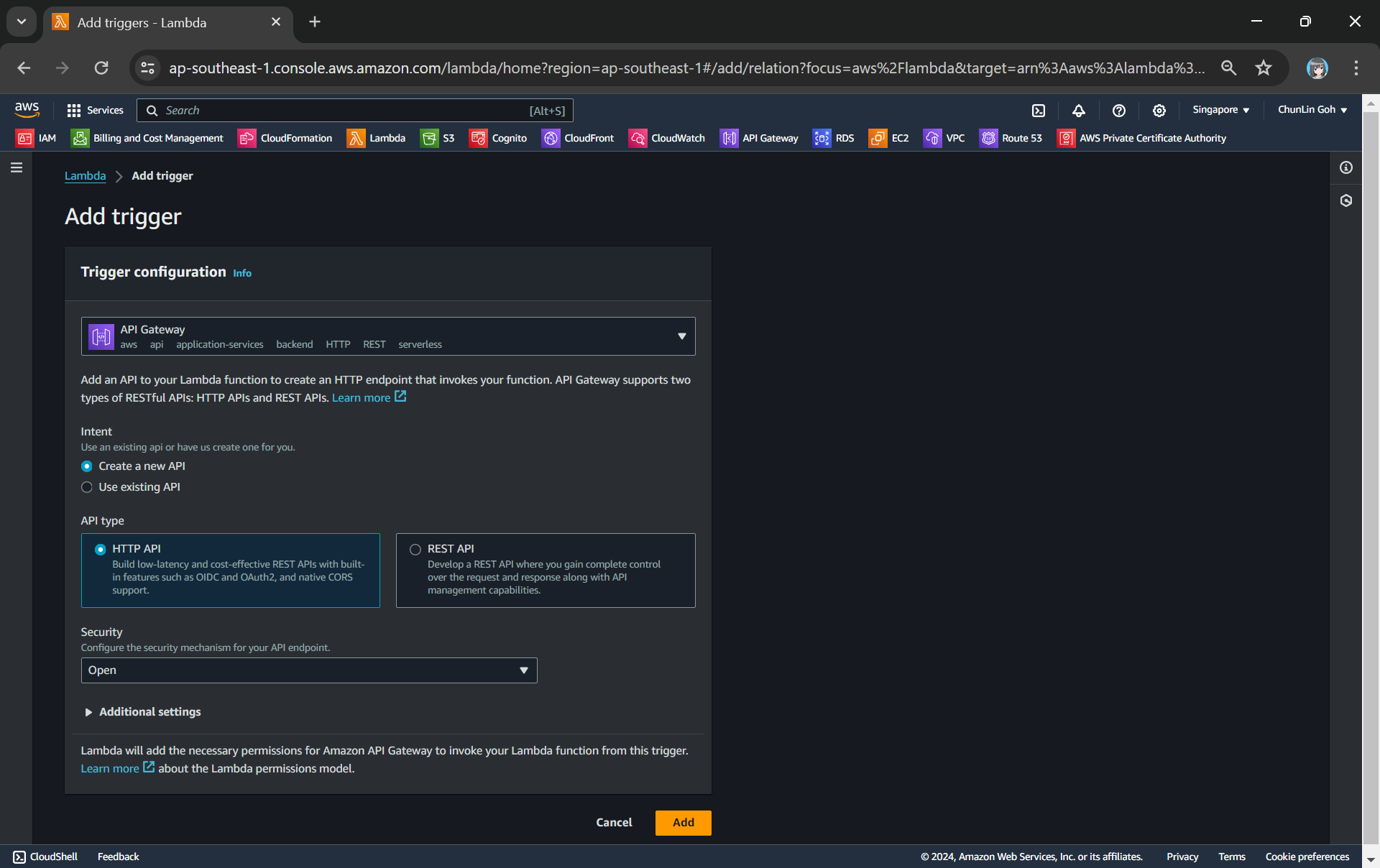
Hence, we need a way to properly handle HTTPS before it reaches ECS. Now, let’s see how we can solve this with API Gateway!
Unit 10: API Gateway
As we discussed earlier, not always, but it is best practice to offload SSL termination to API Gateway because NLB does not handle SSL decryption. The SSL termination happens automatically with API Gateway for HTTPS traffic. It is a built-in feature, so we do not have to worry about manually managing SSL certificates on our backend.
In addition, API Gateway brings extra benefits such as blocking unwanted traffic and ensures only the right users can access our services. It also caches frequent requests, reducing load on our backend. Finally, it is able to log all requests, making troubleshooting faster.
By using API Gateway, we keep our infrastructure secure, efficient, and easy to manage.
Let’s start with a basic setup of API Gateway with NLB by setting up the following required components:
- AWS::ApiGateway::RestApi: The root API that ties everything together. It defines the API itself before adding resources and methods.
- AWS::ApiGateway::VpcLink: Connects API Gateway to the NLB.
- AWS::ApiGateway::Resource: Defines the API endpoint path.
- AWS::ApiGateway::Method: Specifies how the API handles requests (e.g. GET, POST).
- AWS::ApiGateway::Deployment: Deploys the API configuration.
- AWS::ApiGateway::Stage: Assigns a stage (e.g. dev, prod) to the deployment.
Setup Rest API
API Gateway is like a front door to our backend services. Before we define any resources, methods, or integrations, we need to create this front door first, i.e. the AWS::ApiGateway::RestApi resource.
apiGatewayRestApi:
  Type: AWS::ApiGateway::RestApi
  Properties:
    Name: !Sub "${ServiceName}-api-gateway"
    DisableExecuteApiEndpoint: True
    EndpointConfiguration:
      Types:
        - REGIONAL
    Policy: ''
Here we disable the execute-api endpoint because we want to stop AWS from exposing a default execute-api endpoint. We want to enforce access through our own custom domain which we will setup later.
REGIONAL ensures that the API is available only within our AWS region. Setting it to REGIONAL is generally the recommended option for most apps, especially for our Orchard Core CMS, because both the ECS instances and the API Gateway are in the same region. This setup allows requests to be handled locally, which minimises latency. In the future, if our CMS user base grows and is distributed globally, we may need to consider switching to EDGE to serve our CMS to a larger global audience with better performance and lower latency across regions.
Finally, since this API is mainly acting as a reverse proxy to our Orchard Core homepage on ECS, CORS is not needed. We also leave Policy: '' empty means anyone can access the public-facing Orchard Core. Instead, security should be handled by the Orchard Core authentication.
Now that we have our root API, the next step is to connect it to our VPC using VpcLink!
Setup VPC Link
The VPC Link allows API Gateway to access private resources in our VPC, such as our ECS services via the NLB. This connection ensures that requests from the API Gateway can securely reach the Orchard Core CMS hosted in ECS, even though those resources are not publicly exposed.
In simple terms, VPC Link acts as a bridge between the public-facing API Gateway and the internal resources within our VPC.
So in our template, we define the VPC Link and specify the NLB as the target, which means that all API requests coming into the Gateway will be forwarded to the NLB, which will then route them to our ECS tasks securely.
apiGatewayVpcLink:
  Type: AWS::ApiGateway::VpcLink
  Description: "VPC link for API Gateway of Orchard Core"
  Properties:
    Name: !Sub "${ServiceName}-vpc-link"
    TargetArns:
      - !Ref internalNlb
Now that we have set up the VpcLink, which connects our API Gateway to our ECS, the next step is to define how requests will actually reach our ECS. That is where the API Gateway Resource comes into play.
Setup API Gateway Resource
For the API Gateway to know what to do with the incoming requests once they cross that VPC Link bridge, we need to define specific resources, i.e. the URL paths our users will use to access the Orchard Core CMS.
In our case, we use a proxy resource to catch all requests and send them to the backend ECS service. This lets us handle dynamic requests with minimal configuration, as any path requested will be forwarded to ECS.
Using proxy resource is particularly useful for web apps like Orchard Core CMS, where the routes could be dynamic and vary widely, such as /home, /content-item/{id}, /admin/{section}. With the proxy resource, we do not need to define each individual route or API endpoint in the API Gateway. As the CMS grows and new routes are added, we also will not need to constantly update the API Gateway configuration.
apiGatewayRootProxyResource:
  Type: AWS::ApiGateway::Resource
  Properties:
    RestApiId: !Ref apiGatewayRestApi
    ParentId: !GetAtt apiGatewayRestApi.RootResourceId
    PathPart: '{proxy+}'
  DependsOn:
    - apiGatewayRestApi
After setting up the resources and establishing the VPC link to connect API Gateway to our ECS instances, the next step is to define how we handle incoming requests to those resources. This is where the AWS::ApiGateway::Method comes in. It defines the specific HTTP methods that API Gateway should accept for a particular resource.
Setup Method
The Resource component above is used to define where the requests will go. However, just defining the path alone is not enough to handle incoming requests. We need to tell API Gateway how to handle requests that come to those paths. This is where the AWS::ApiGateway::Method component comes into play.
For a use case like hosting Orchard Core CMS, the following configuration can be a good starting point.
apiGatewayRootMethod:
  Type: AWS::ApiGateway::Method
  Properties:
    HttpMethod: ANY
    AuthorizationType: NONE
    ApiKeyRequired: False
    RestApiId: !Ref apiGatewayRestApi
    ResourceId: !GetAtt apiGatewayRestApi.RootResourceId
    Integration:
      ConnectionId: !Ref apiGatewayVpcLink
      ConnectionType: VPC_LINK
      Type: HTTP_PROXY
      IntegrationHttpMethod: ANY
      Uri: !Sub "http://${internalNlb.DNSName}"
  DependsOn:
    - apiGatewayRootProxyResource

apiGatewayRootProxyMethod:
  Type: AWS::ApiGateway::Method
  Properties:
    ApiKeyRequired: False
    RestApiId: !Ref apiGatewayRestApi
    ResourceId: !Ref apiGatewayRootProxyResource
    HttpMethod: ANY
    AuthorizationType: NONE
    RequestParameters:
      method.request.path.proxy: True
    Integration:
      ConnectionId: !Ref apiGatewayVpcLink
      ConnectionType: VPC_LINK
      Type: HTTP_PROXY
      RequestParameters:
        integration.request.path.proxy: method.request.path.proxy
      CacheKeyParameters:
        - method.request.path.proxy
      IntegrationHttpMethod: ANY
      IntegrationResponses:
        - StatusCode: 200
          SelectionPattern: 200
      Uri: !Sub "http://${internalNlb.DNSName}/{proxy}"
  DependsOn:
    - apiGatewayRootProxyResource
    - apiGatewayVpcLink
By setting up both the root method and the proxy method, the API Gateway can handle both general traffic via the root method and dynamic path-based traffic via the proxy method in a flexible way. This reduces the need for additional methods and resources to manage various paths.

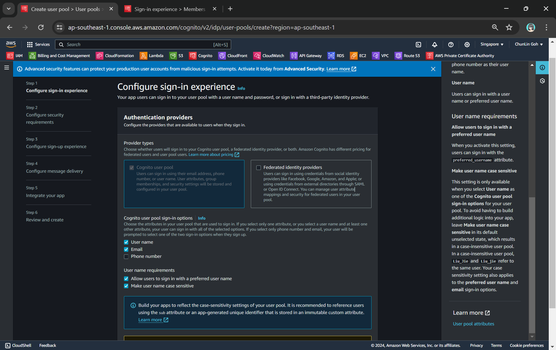
Since Orchard Core is designed for browsing, updating, and deleting content, as a start, we may need support for multiple HTTP methods. By using ANY, we are ensuring that all these HTTP methods are supported without having to define separate methods for each one.
Setting AuthorizationType to NONE is a good starting point, especially in cases where we are not expecting to implement authentication directly at the API Gateway level. Instead, we are relying on Orchard Core built-in authentication module, which already provides user login, membership, and access control. Later, if needed, we can enhance security by adding authentication layers at the API Gateway level, such as AWS IAM, Cognito, or Lambda authorisers.
Similar to the authorisation, setting ApiKeyRequired to False is also a good choice for a starting point, especially since we are not yet exposing a public API. The setup above is primarily for routing requests to Orchard Core CMS. We could change if we need to secure our CMS API endpoints in the future when 3rd-party integrations or external apps need access to the CMS API.
Up to this point, API Gateway has a Resource and a Method, but it still does not know where to send the request. That is where Integration comes in. In our setup above, it tells API Gateway to use VPC Link to talk to the ECS. It also makes API Gateway act as a reverse proxy by setting Type to HTTP_PROXY. It will simply forward all types of HTTP requests to Orchard Core without modifying them.
Even though API Gateway enforces HTTPS for external traffic, it decrypts (aka terminates SSL), validates the request, and then forwards it over HTTP to NLB within the AWS private network. Since this internal communication happens securely inside AWS, the Uri is using HTTP.
After setting up the resources and methods in API Gateway, we are essentially defining the blueprint for our API. However, these configurations are only in a draft state so they are not yet live and accessible to our end-users. We need a step called Deployment to publish the configuration.
Setup Deployment
Without deploying, the changes we discussed above are just concepts and plans. We can test them within CloudFormation, but they will not be real in the API Gateway until they are deployed.
There is an important thing to take note is that API Gateway does not automatically detect changes in our CloudFormation template. If we do not create a new deployment, our changes will not take effect in the live environment. So, we must force a new deployment by changing something in AWS::ApiGateway::Deployment.
Another thing to take note is that a new AWS::ApiGateway::Deployment will not automatically be triggered when we update our API Gateway configurations unless the logical ID of the deployment resource itself changes. This means that every time we make changes to our API Gateway configurations, we need to manually change the logical ID of the AWS::ApiGateway::Deployment. The reason CloudFormation does not automatically redeploy is to avoid unnecessary changes or disruptions.
apiGatewayDeployment202501011048:
  Type: AWS::ApiGateway::Deployment
  Properties:
    RestApiId: !Ref apiGatewayRestApi
  DependsOn:
    - apiGatewayRootMethod
In the template above, we append a timestamp 202501011048 to the logical ID of the Deployment. This way, even if we make multiple deployments on the same day, each will have a unique logical ID due to the timestamp.
Deployment alone does not make our API available to the users. We still need to assign it to a specific Stage to ensure it has a versioned endpoint with all configurations applied.
Setup Stage
A Stage in API Gateway is a deployment environment that allows us to manage and control different versions of our API. It acts as a live endpoint for clients to interact with our API. Without a Stage, the API exists but is not publicly available. We can create stages like dev, test, and prod to separate development and production traffic.
apiGatewayStage:
  Type: AWS::ApiGateway::Stage
  Properties:
    StageName: !Ref ApiGatewayStageName
    RestApiId: !Ref apiGatewayRestApi
    DeploymentId: !Ref apiGatewayDeployment202501011048
    MethodSettings:
      - ResourcePath: '/*'
        HttpMethod: '*'
        ThrottlingBurstLimit: 100
        ThrottlingRateLimit: 50
    Tags:
      - Key: Stack
        Value: !Ref AWS::StackName
For now, we will use production as the default stage name to keep things simple. This will help us get everything set up and running quickly. Once we are ready for more environments, we can easily update the ApiGatewayStageName in the Parameters based on our environment setup.
MethodSettings are configurations defining how requests are handled in terms of performance, logging, and throttling. Using /* and * is perfectly fine at the start as our goal is to apply global throttling and logging settings for all our Orchard Core routes in one go. However, in the future we might want to adjust the settings as follows:
- Content Modification (
POST,PUT,DELETE): Stricter throttling and more detailed logging. - Content Retrieval (
GET): More relaxed throttling for GET requests since they are usually read-only and have lower impact.
Having a burst and rate limit is useful for protecting our Orchard Core backend from excessive traffic. Even if we have a CMS with predictable traffic patterns, having rate limiting helps to prevent abuse and ensure fair usage.

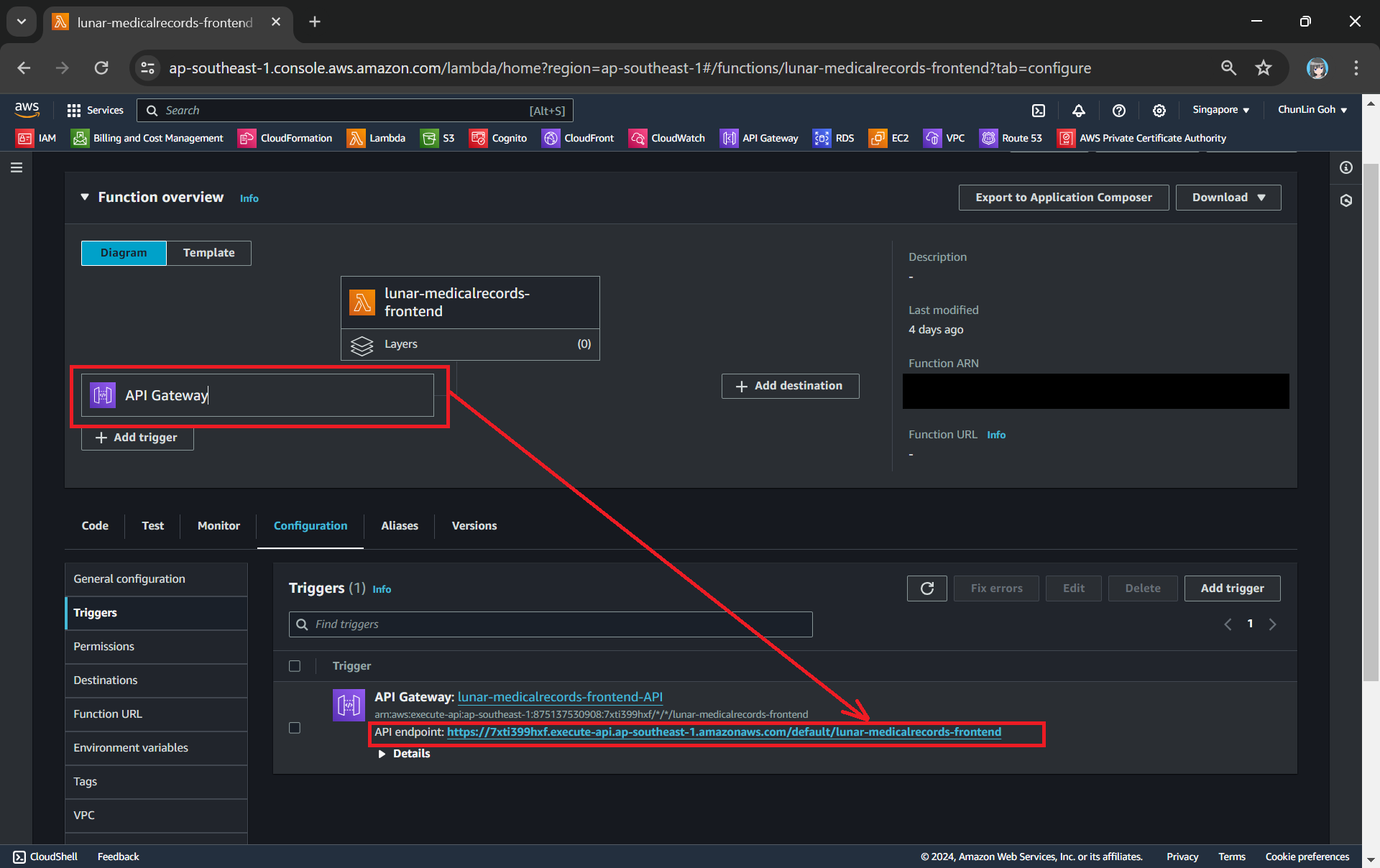
Unit 11: Route53 for API Gateway
Now that we have successfully set up API Gateway, it is accessible through an AWS-generated URL, i.e. something like https://xxxxxx.execute-api.ap-southeast-5.amazonaws.com/production which is functional but not user-friendly. Hence, we need to setup a custom domain for it so that it easier to remember, more professional, and consistent with our branding.
AWS provides a straightforward way to implement this using two key configurations:
- AWS::ApiGateway::DomainName – Links our custom domain to API Gateway.
- AWS::ApiGateway::BasePathMapping – Organises API versions and routes under the same domain.
Setup Hosted Zone and DNS
Since I have my domain on GoDaddy, I will need to migrate DNS management to AWS Route 53 by creating a Hosted Zone.

After creating a Hosted Zone in AWS, we need to manually copy the NS records to GoDaddy. This step is manual anyway, so we will not be automating this part of setup in CloudFormation. In addition, hosted zones are sensitive resources and should be managed carefully. We do not want hosted zones to be removed when our CloudFormation stacks are deleted too.
Once the switch is done, we can go back to our CloudFormation template to setup the custom domain name for our API Gateway.
Setup Custom Domain Name for API Gateway
API Gateway requires an SSL/TLS certificate to use a custom domain.
apiGatewayCustomDomainCert:
Type: AWS::CertificateManager::Certificate
Properties:
DomainName: !Ref HostedZoneName
ValidationMethod: 'DNS'
DomainValidationOptions:
- DomainName: !Sub "${CmsHostname}.{HostedZoneName}"
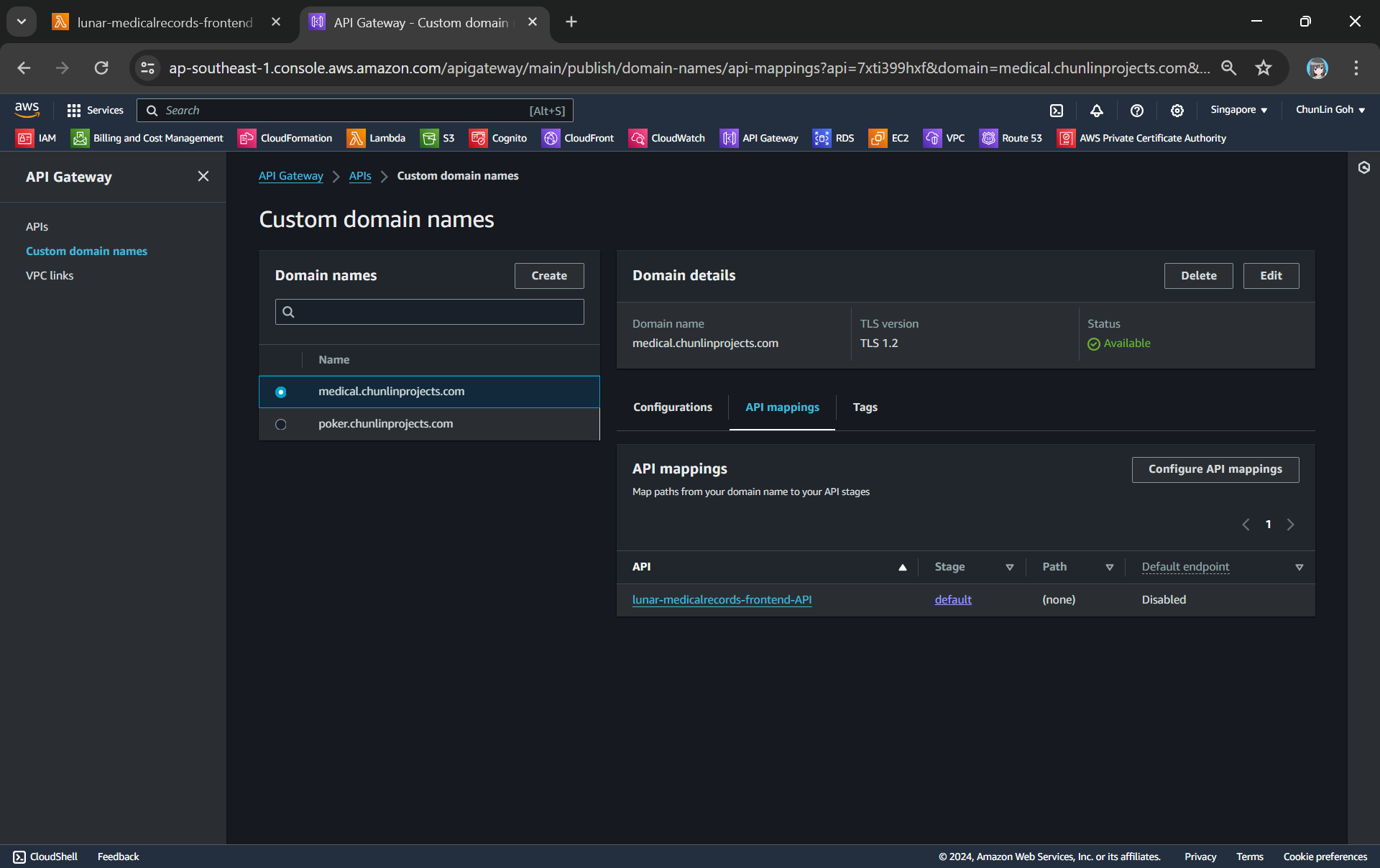
HostedZoneId: !Ref HostedZoneId
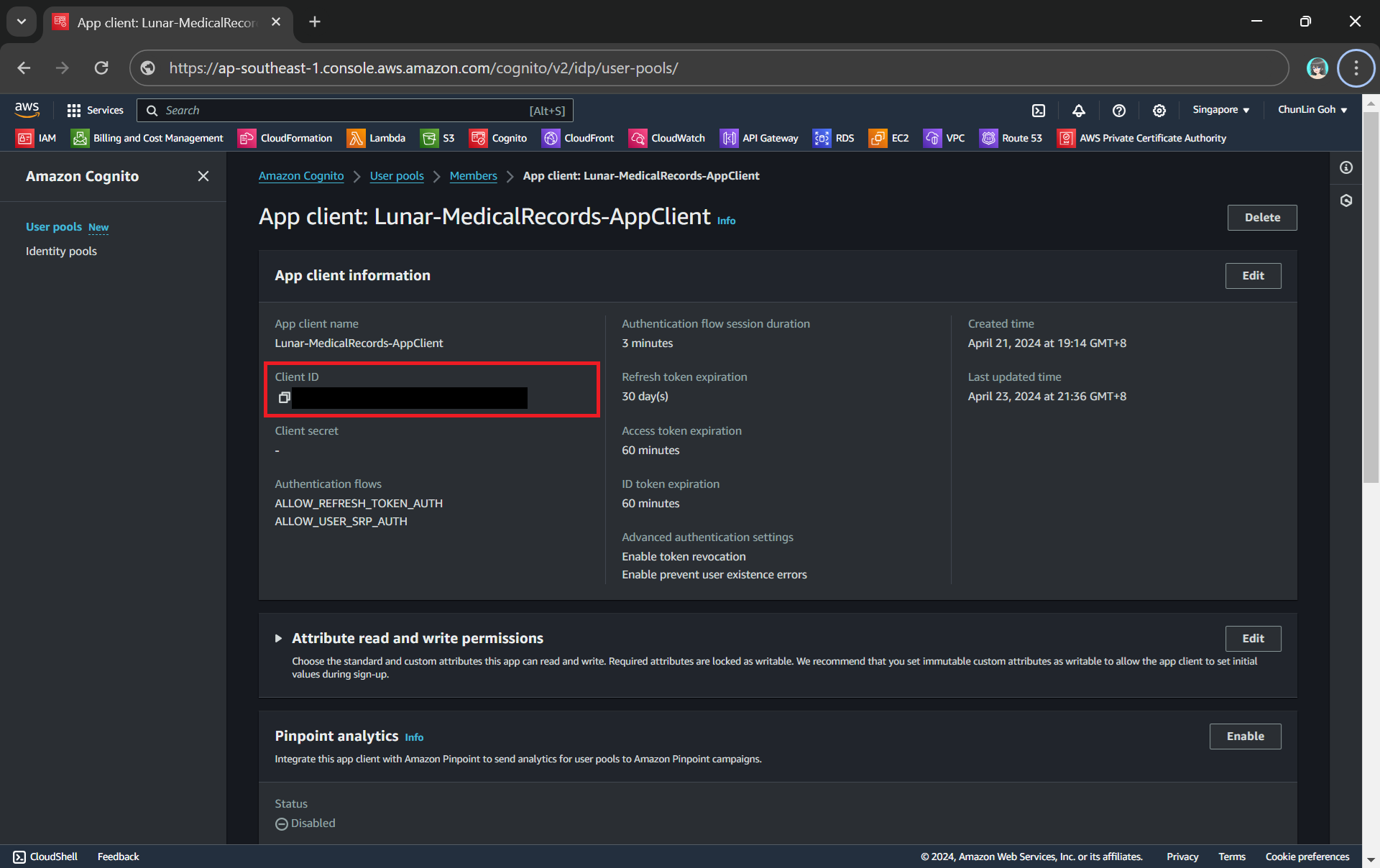
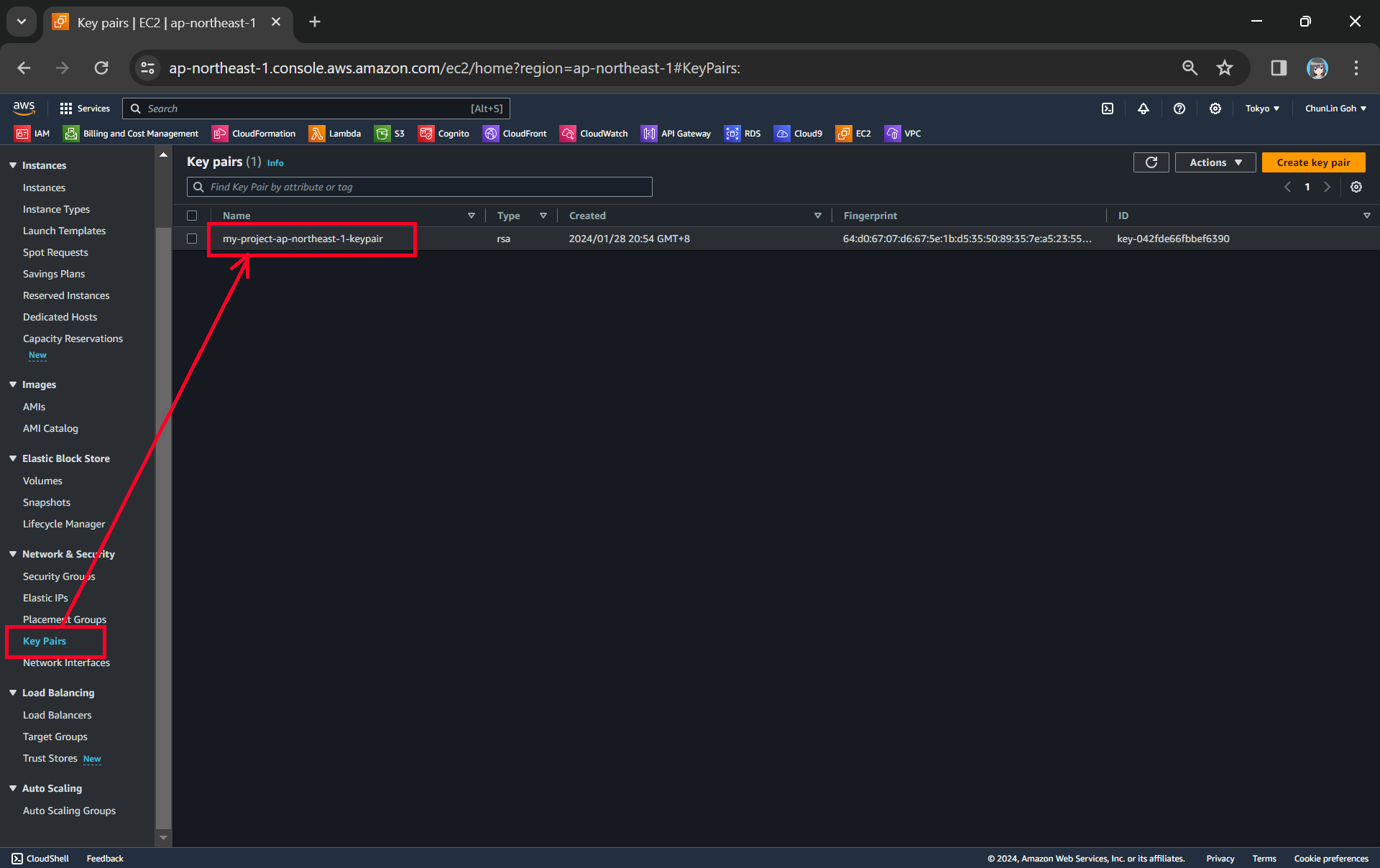
Take note that please update the DomainNames in the template above to use your domain name. Also, the HostedZoneId can be retrieved from the AWS Console under “Hosted zone details” in the screenshot above.
In the resource, DomainValidationOptions tells CloudFormation to use DNS validation. When we use the AWS::CertificateManager::Certificate resource in a CloudFormation stack, domain validation is handled automatically if all three of the following are true:
- We are using DNS validation;
- The certificate domain is hosted in Amazon Route 53;
- The domain resides in our AWS account.
However, if the certificate uses email validation, or if the domain is not hosted in Route 53, then the stack will remain in the CREATE_IN_PROGRESS state. Here, we will show how we can log in to AWS Console to manually set up DNS validation.

After that, we need to choose the Create records in Route 53 button to create records. The Certificate status page should open with a status banner reporting Successfully created DNS records. According to the documentation, our new certificate might continue to display a status of Pending validation for up to 30 minutes.

Now that the SSL certificate is ready and the DNS validation is done, we will need to link the SSL certificate to our API Gateway using a custom domain. We are using RegionalCertificateArn, which is intended for a regional API Gateway.
apiGatewayCustomDomainName:
  Type: AWS::ApiGateway::DomainName
  Properties:
    RegionalCertificateArn: !Ref apiGatewayCustomDomainCert
    DomainName: !Sub "${CmsHostname}.{HostedZoneName}"
    EndpointConfiguration:
      Types:
        - REGIONAL
    SecurityPolicy: TLS_1_2
This allows our API to be securely accessed using our custom domain. We also set up a SecurityPolicy to use the latest TLS version (TLS 1.2), ensuring that the connection is secure and follows modern standards.
Even though it is optional, it is a good practice to specify the TLS version for both security and consistency, especially for production environments. Enforcing a TLS version helps avoid any potential vulnerabilities from outdated protocols.
Setup Custom Domain Routing
Next, we need to create a base path mapping to map the custom domain to our specific API stage in API Gateway.
The BasePathMapping is the crucial bridge between our custom domain and our API Gateway because when users visit our custom domain, we need a way to tell AWS API Gateway which specific API and stage should handle the incoming requests for that domain.
apiGatewayCustomDomainBasePathMapping:
  Type: AWS::ApiGateway::BasePathMapping
  Properties:
    DomainName: !Ref apiGatewayCustomDomainName
    RestApiId: !Ref apiGatewayRestApi
    Stage: !Ref apiGatewayStage
While the BasePathMapping connects our custom domain to a specific stage inside our API Gateway, we need to setup DNS routing outside AWS which handles the DNS resolution.
The RecordSet creates a DNS record (typically an A or CNAME record) that points to the API Gateway endpoint. Without this record, DNS systems outside AWS will not know where to direct traffic for our custom domain.
apiGatewayCustomDomainARecord:
  Type: AWS::Route53::RecordSet
  Properties:
    HostedZoneName: !Sub "${HostedZoneName}."
    Name: !Sub "${CmsHostname}.{HostedZoneName}"
    Type: A
    AliasTarget:
      DNSName: !GetAtt apiGatewayCustomDomainName.RegionalDomainName
      HostedZoneId: !GetAtt apiGatewayCustomDomainName.RegionalHostedZoneId
There is one interesting stuff to take note here is that when we use an AWS::Route53::RecordSet that specifies HostedZoneName, we must include a trailing dot (for example, chunlinprojects.com.) as part of the HostedZoneName. Otherwise, we can also choose to specify HostedZoneId instead, but never specifying both.
For API Gateway with a custom domain, AWS recommends using an Alias Record (which is similar to an A record) instead of a CNAME because the endpoint for API Gateway changes based on region and the nature of the service.
Alias records are a special feature in AWS Route 53 designed for pointing domain names directly to AWS resources like API Gateway, ELB, and so on. While CNAME records are often used in DNS to point to another domain, Alias records are unique to AWS and allow us to avoid extra DNS lookup costs.
For the HostedZoneId of AliasTarget, it is the Route 53 Hosted Zone ID of the API Gateway, do not mess up with the ID of our own hosted zone in Route 53.
Finally, please take note that when we are creating an alias resource record set, we need to omit TTL.
Reference 01: ECS Cluster
As we move forward with hosting Orchard Core CMS, let’s go through a few hosting options available within AWS, as listed below.
- EC2 (Elastic Compute Cloud): A traditional option for running virtual machines. We can fully control the environment but need to manage everything, from scaling to OS patching;
- Elastic Beanstalk: PaaS optimised for traditional .NET apps on Windows/IIS, not really suitable for Orchard Core which runs best on Linux containers with Kestrel;
- Lightsail: A traditional VPS (Virtual Private Server), where we manage the server and applications ourselves. It is a good fit for simple, low-traffic websites but not ideal for scalable workloads like Orchard Core CMS.
- EKS (Elastic Kubernetes Service): A managed Kubernetes offering from AWS. It allows us to run Kubernetes clusters, which are great for large-scale apps with complex micro-services. However, managing Kubernetes adds complexity.
- ECS (Elastic Container Service): A service designed for running containerised apps. We can run containers on serverless Fargate or EC2-backed clusters.
The reason why we choose ECS is because it offers a scalable, reliable, and cost-effective way to deploy Orchard Core in a containerised environment. ECS allows us to take advantage of containerisation benefits such as isolated, consistent deployments and easy portability across environments. With built-in support for auto-scaling and seamless integration with AWS services like RDS for databases, S3 for media storage, and CloudWatch for monitoring, ECS ensures high availability and performance.
In ECS, we can choose to use either Fargate or EC2-backed ECS for hosting Orchard Core, depends on our specific needs and use case. For highly customised, predictable, or resource-intensive workloads CMS, EC2-based ECS might be more appropriate due to the need for fine-grained control over resources and configurations.

There is an official documentation on how to an setup ECS cluster. Hence, we will not discuss in depth about how to set it up. Instead, we will focus on some of the key points that we need to take note of.

While we can technically use any Linux AMI for running ECS tasks, the Amazon ECS-Optimised AMI offers several key benefits and optimisations that make it a better choice, particularly for ECS workloads. The Amazon ECS-Optimised AMI is designed and optimised by AWS to run ECS tasks efficiently on EC2 instances. By using the ECS-Optimised AMI, we benefit from pre-installed ECS agent + Docker as well as optimised configuration for ECS. Those AMI look for agent configuration data in the /etc/ecs/ecs.config file when the container agent starts. That’s why can specify this configuration data at launch with Amazon EC2 user data, as shown below.
containerInstances:
  Type: AWS::EC2::LaunchTemplate
  Properties:
    LaunchTemplateName: "asg-launch-template"
    LaunchTemplateData:
      ImageId: !Ref EcsAmi
      InstanceType: "t3.large"
      IamInstanceProfile:
        Name: !Ref ec2InstanceProfile
      SecurityGroupIds:
        - !Ref ecsContainerHostSecurityGroup
      # This injected configuration file is how the EC2 instance
      # knows which ECS cluster it should be joining
      UserData:
        Fn::Base64: !Sub |
         #!/bin/bash -xe
         echo "ECS_CLUSTER=core-cluster" >> /etc/ecs/ecs.config
      # Disable IMDSv1, and require IMDSv2
      MetadataOptions:
        HttpEndpoint: enabled
        HttpTokens: required
As shown in the above CloudFormation template, instead of hardcoding an AMI ID which will become outdated over time, we have a parameter to ensure that the cluster always provisions instances using the most recent Amazon Linux 2023 ECS-optimised AMI.
EcsAmi:
  Description: The Amazon Machine Image ID used for the cluster
  Type: AWS::SSM::Parameter::Value<AWS::EC2::Image::Id>
  Default: /aws/service/ecs/optimized-ami/amazon-linux-2023/recommended/image_id
Also, the EC2 instances need access to communicate with the ECS service endpoint. This can be through an interface VPC endpoint or through our EC2 instances having public IP addresses. In our case, we are placing our EC2 instances in private subnets, so we use the Network Address Translation (NAT) to provide this access.
ecsNatGateway:
  Type: AWS::EC2::NatGateway
  Properties:
    AllocationId: !GetAtt ecsEip.AllocationId
    SubnetId: !Ref publicSubnet1
Unit 12: ECS Task Definition and Service
This ECS cluster definition is just the starting point. Next, we will define how the containers run and interact through AWS::ECS::TaskDefinition.
ecsTaskDefinition:
  Type: AWS::ECS::TaskDefinition
  Properties:
    Family: !Ref ServiceName
    TaskRoleArn: !GetAtt iamRole.Arn
    ContainerDefinitions:
      - Name: !Ref ServiceName
        Image: !Ref OrchardCoreImage
        LogConfiguration:
          LogDriver: awslogs
          Options:
            awslogs-group: !Sub "/ecs/${ServiceName}-log-group"
            awslogs-region: !Ref AWS::Region
            awslogs-stream-prefix: ecs
        PortMappings:
          - ContainerPort: 5000
            HostPort: 80
            Protocol: tcp
        Cpu: 256
        Memory: 1024
        MemoryReservation: 512
        Environment:
          - Name: DatabaseEndpoint
            Value: !GetAtt cmsDBInstance.Endpoint.Address
        Essential: true
        HealthCheck:
          Command:
            - CMD-SHELL
            - "wget -q --spider http://localhost:5000/health || exit 1"
          Interval: 30
          Timeout: 5
          Retries: 3
          StartPeriod: 30
In the setup above, we are sending logs to CloudWatch Logs so that we can centralise logs from all ECS tasks, making it easier to monitor and troubleshoot our containers.
By default, ECS is using bridge network mode. In bridge mode, containers do not get their own network interfaces. Instead, the container port (5000) must be mapped to a port on the host EC2 instance (80). Without this mapping, the Orchard Core on EC2 would not be reachable from outside. The reason we set the ContainerPort: 5000 in is to match the port our Orchard Core app is exposed on within the Docker container.
As CMS platforms like Orchard Core generally require more memory for smooth operations, especially in production environments with more traffic, it is better to start with a CPU allocation like 256 (0.25 vCPU) and 1024 MB for memory, depending on expected load.
For the MemoryReservation which is a guaranteed amount of memory for our container, we set it to be 512 MB of memory. By reserving memory, we are ensuring that your container has enough memory to run reliably. Orchard Core, being a modular CMS, can consume more memory depending on the number of features/modules you have enabled. Later if we realise Orchard Core does not need that much guaranteed memory, we can leave MemoryReservation lower. The key idea is to reserve enough memory to ensure stable operations without overcommitting.
Next, we have Essential where we set it to true. This property specifies whether the container is essential to the ECS task. We set it to true so that ECS will treat this Orchard Core container as vital for the task. If the container stops or fails, ECS will stop the entire task. Otherwise, ECS will not automatically stop the task if this Orchard Core container fails, which could lead to issues, especially in a production environment.
Finally, we must not forget about HealthCheck. In most web apps like Orchard Core, a simple HTTP endpoint /health is normally used as a health check. Here, we need to understand that many minimal container images like ECS-optimised AMIs do not include curl by default to keep them lightweight. However, wget is often available by default, making it a good alternative for checking if an HTTP endpoint is reachable. Hence, in the template above, ECS is using wget to check the /health endpoint on port 5000. If it receives an error, the container is considered unhealthy.

curl or wget is available in the image.Once the TaskDefinition is set up, it defines the container specs. However, the ECS service is needed to manage how and where the task runs within the ECS cluster. We need the ECS service tells ECS how to run the task, manage it, and keep it running smoothly.
ecsService:
  Type: AWS::ECS::Service
  DependsOn:
    - iamRole
    - internalNlb
    - nlbTargetGroup
    - internalNlbListener
  Properties:
    Cluster: !Ref ecsCluster
    DesiredCount: 2
    DeploymentConfiguration:
      MaximumPercent: 200
      MinimumHealthyPercent: 50
    LoadBalancers:
      - ContainerName: !Ref ServiceName
        ContainerPort: 5000
        TargetGroupArn: !Ref nlbTargetGroup
    PlacementStrategies:
      - Type: spread
        Field: attribute:ecs.availability-zone
      - Type: spread
        Field: instanceId
    TaskDefinition: !Ref ecsTaskDefinition
    ServiceName: !Ref ServiceName
    Role: !Sub "arn:${AWS::Partition}:iam::${AWS::AccountId}:role/aws-service-role/ecs.amazonaws.com/AWSServiceRoleForECS"
    HealthCheckGracePeriodSeconds: 60
The DesiredCount is the number of tasks (or containers) we want ECS to run at all times for Orchard Core app. In this case, we set it to 2 which means that ECS will try to keep exactly 2 tasks running for our service. Setting it to 2 helps ensure that we have redundancy. If one task goes down, the other task can continue serving, ensuring that our CMS stays available and resilient.
Based on the number of DesiredCount, we indicate that during deployment, ECS can temporarily run up to 4 tasks (MaximumPercent: 200) and at least 1 task (MinimumHealthyPercent: 50) must be healthy during updates to ensure smooth deployment.
The LoadBalancers section in the ECS service definition is where we link our service to the NLB that we set up earlier, ensuring that the NLB will distribute the traffic to the correct tasks running within the ECS service. Also, since our container is configured to run on port 5000 as per our Dockerfile, this is the port we use.
Next, we have PlacementStrategies to help us control how our tasks are distributed across different instances and availability zones, making sure our CMS is resilient and well-distributed. Here, attribute:ecs.availability-zone ensures the tasks are spread evenly across different availability zones within the same region. At the same time, Field: instanceId ensures that our tasks are spread across different EC2 instances within the cluster.
Finally, it is a good practice to set a HealthCheckGracePeriodSeconds to give our containers some time to start and become healthy before ECS considers them unhealthy during scaling or deployments.
Unit 13: CloudWatch Alarm
To ensure we effectively monitor the performance of Orchard Core on our ECS service, we also need to set up CloudWatch alarms to track metrics like CPU utilisation, memory utilisation, health check, running task count, etc.
We set up the following CloudWatch alarm to monitor CPU utilisation for our ECS service. This alarm triggers if the CPU usage exceeds 75% for a specified period (5 minutes). By doing this, we can quickly identify when our service is under heavy load, which helps us take action to prevent performance issues.
highCpuUtilizationAlarm:
  Type: AWS::CloudWatch::Alarm
  Properties:
    AlarmName: !Sub "${AWS::StackName}-high-cpu"
    AlarmDescription: !Sub "ECS service ${AWS::StackName}: Cpu utilization above 75%"
    Namespace: AWS/ECS
    MetricName: CPUUtilization
    Dimensions:
      - Name: ClusterName
        Value: !Ref ecsCluster
      - Name: ServiceName
        Value: !Ref ServiceName
    Statistic: Average
    Period: 60
    EvaluationPeriods: 5
    Threshold: 75
    ComparisonOperator: GreaterThanOrEqualToThreshold
    TreatMissingData: notBreaching
    ActionsEnabled: true
    AlarmActions: []
    OKActions: []
Even if we leave AlarmActions and OKActions as empty arrays, the alarm state will still be visible in the AWS CloudWatch Console. We can monitor the alarm state directly on the CloudWatch dashboard.
Similar to the CPU utilisation alarm above, we have another alarm to trigger when the count of running tasks is 0 (less than 1) for 5 consecutive periods, indicating that there have been no running tasks for a full 5 minutes.
noRunningTasksAlarm:
  Type: AWS::CloudWatch::Alarm
  Properties:
    AlarmName: !Sub "${AWS::StackName}-no-task"
    AlarmDescription: !Sub "ECS service ${AWS::StackName}: No running ECS tasks for more than 5 mins"
    Namespace: AWS/ECS
    MetricName: RunningTaskCount
    Dimensions:
      - Name: ClusterName
        Value: !Ref ecsCluster
      - Name: ServiceName
        Value: !Ref ServiceName
    Statistic: Average
    Period: 60
    EvaluationPeriods: 5
    Threshold: 1
    ComparisonOperator: LessThanThreshold
    TreatMissingData: notBreaching
    ActionsEnabled: true
    AlarmActions: []
    OKActions: []

By monitoring these key metrics, we can proactively address any performance or availability issues, ensuring our Orchard Core CMS runs smoothly and efficiently.
Wrap-Up
Setting up Orchard Core on ECS with CloudFormation does have its complexities, especially with the different moving parts like API Gateway, load balancers, and domain configurations. However, once we have the infrastructure defined in CloudFormation, it becomes much easier to deploy, update, and manage our AWS environment. This is one of the key benefits of using CloudFormation, as it gives us consistency, repeatability, and automation in our deployments.

The heavy lifting is done up front, and after that, it is mostly about making updates to our CloudFormation stack and redeploying without having to worry about manually reconfiguring everything.