I like to explore interesting new technologies. I also love to learn more from the materials available on Microsoft Virtual Academy, Google Developers channel, and several other tech/dev events.
Recently, I was asked to cut down the cost of hosting an ASP .NET Core website on Azure. The website is originally hosted on Azure Web App so there is a fixed cost to it that we need to pay per month. Hence, the first solution that comes to my mind is to move it from Web App to Function because the website is a static website and it is not expecting large group of visitors in any given point of time.
So why do I choose to use Azure Function? Unlike the Web Apps, Functions provide the Consumption Plan where instances of the Functions host are dynamically added and removed based on the number of incoming events. This serverless plan scales automatically, and we are billed only when the Functions are running. Hence, when we switch to use Azure Function to serve the static website with the Consumption Plan, we will be able to save significantly.
Serve Static Content with Azure Function
How do we serve static website with Azure Functions?
There are many online tutorials about this but none of them that I found are based on the latest Azure Portal GUI in 2020. So hopefully my article here will help people out there who are using the latest Azure Portal.
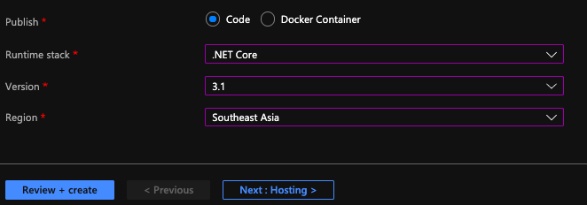
The following screenshot shows the setup of my Azure Function.
[Image Caption: Azure Function with .NET Core 3.1.]
After that, we will create a HTTP triggered function in the Azure Function.
Then for the Function itself, we can add the following code in run.csx.
using Microsoft.AspNetCore.Mvc;

public static async Task<IActionResult> Run(HttpRequest req, ILogger log){

    string pathValue = req.Path.Value;

    ...

    return new FileStreamResult(
        File.OpenRead(
            @"d:\home\site\wwwroot\web-itself\website\index.html"),
            "text/html; charset=UTF-8");
}
The pathValue helps the Function to be able to serve different web pages based on different value in the URL path. For example, /page1 will load page1.html and /page2 will load page2.html.
If the Function you build is only to serve a single HTML file, then you can just directly return the FileStreamResult without relying on the pathValue.
Configure the Route Template
To have the pathValue working as expected, we first need to configure the route template of the Function. To do so, we can head to the Integration tab of the Function, as shown in the screenshot below.
[Image Caption: Editing the Route Template.]
For the Route Template, we set it to be “web-itself/{page?}” because web-itself is the name of our Function in this case. The question mark in the “{page?}” means that the page is an optional argument in the URL.
So why do we have to include the Function name “web-itself” in the Route Template? The values, according to the documentation, should be a relative path. Since, by default, the Function URL is “xxx.azurewebsites.net/api/web-itself”, so the relative path needs to start from “web-itself”.
Also, since this is going to be an URL of our website, we can change the authorisation level to be “Anonymous” and set GET as the only accepted HTTP method.
Upload the Static Files
So where do we upload the static files to? As the code above shows, the file actually sit in the d:\home\site\wwwroot. How do we upload the static files to this directory?
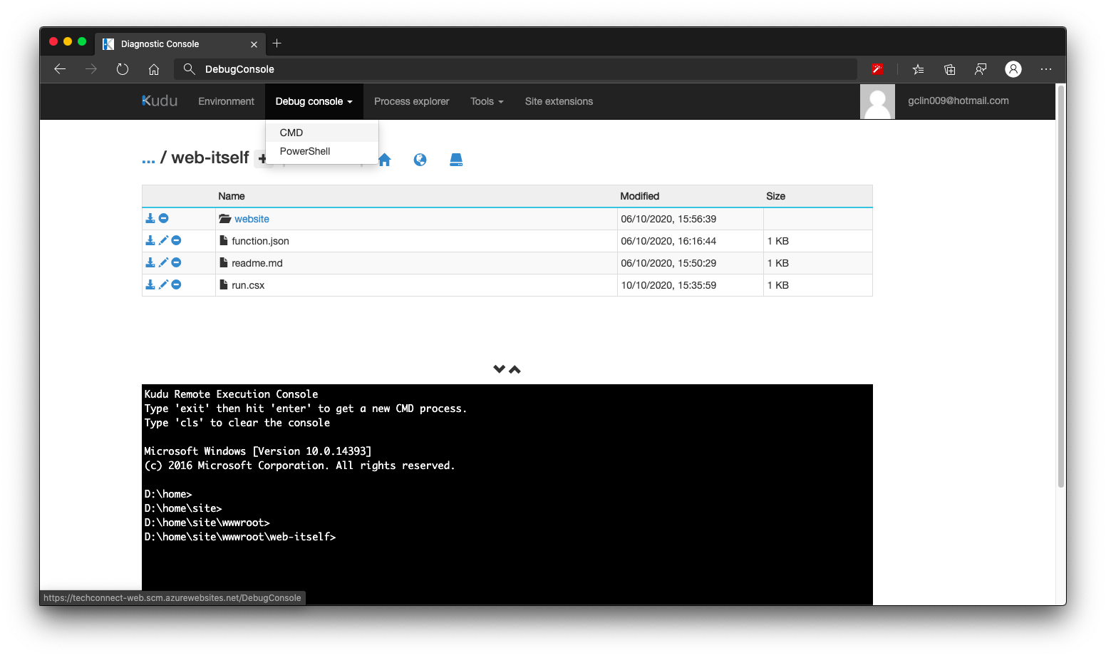
We need to head to the Kudu console of the Azure Function, and click on the CMD menu item, as shown below. By the way, Kudu console can be found under Development Tools > Advanced Tools > Go of the Azure Function on the Portal.
[Image Caption: Kudu console of the Azure Function.]
We then navigate to the folder which keeps the run.csx of the Function (which is web-itself in my case here). Then we can create a folder called website, for example, to host our static content. What we need to do after this is just uploading the HTML files to this website folder.
Handle JavaScript, CSS, and Other Static Files
How about other static files such as JavaScript, CSS, and images?
Yes, we can use the same way above to serve these files. However, that might be too troublesome because each of them has different MIME Type we need to specify.
So another way of doing that is to store all these files on Azure Storage. So the links in the HTML will be absolute URLs to the files on the Azure Storage.
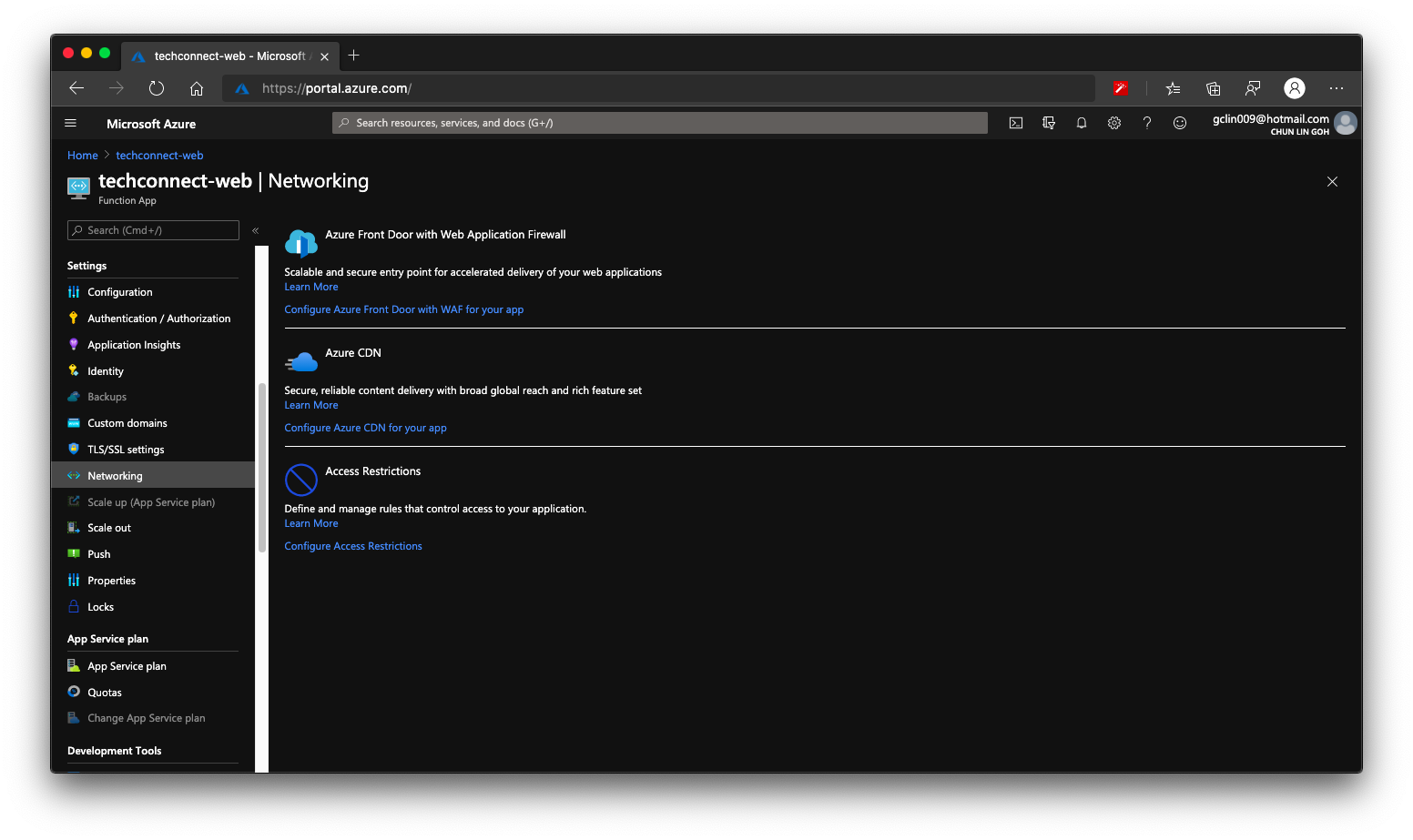
Finally we can enable Azure CDN for our Azure Function. So that if next time we need to move back to host our web pages on Azure Web App or even Azure Storage, we don’t have to change our CNAME again.
[Image Caption: Both Azure CDN and Azure Front Door is available in Azure Functions.]
Two years ago when I visited Microsoft Singapore office, their engineers, Chun Siong and Say Bin, gave me Satya Nadella’s book, Hit Refresh, as well as a Raspberry Pi 3 as gift.
In fact I also got another Raspberry Pi from my brother few years ago and it was running on Windows 10 IoT. It is now in my office together with monitor, keyboard, and mouse. Due to the covid lockdown, I am not allowed to go back to office yet. Hence, I think it’s time to see how we can setup this new Raspberry Pi for headless SSH access with my MacBook.
The method I use here is the headless approach which is suitable if you don’t have access to the GUI to set up a wireless LAN on the Raspberry Pi. Hence, you don’t need to connect monitor, external keyboard, or mouse to the Raspberry Pi at all.
[Image Caption: Enjoying tea break with Chun Siong (Left 1) and Say Bin (Right 2) in October 2018.]
Step 0: Things to Purchase
Besides the Raspberry Pi, we also need to get some other things ready first before we can proceed to setup the device. Most of the things here I bought from Challenger.
Item 1: Toshiba microSDHC UHS-I Card 32GB with SD Adapter
Raspberry Pi uses a microSD card as a hard drive. We can either use a Class 10 microSD card or UHS for Ultra High Speed. Here we are using UHS Class 1. The reason why we do not choose anything greater than 32GB is also because according to the SD specifications, any SD card larger than 32GB is an SDXC card and has to be formatted with the exFAT filesystem which is not supported yet by the Raspberry Pi bootloader. There is of course solutions for this if more SD space is needed for your use cases, please read about it more on Raspberry Pi documentation. The microSD card we choose here is a 32GB SDHC using FAT32 file system which is supported by the Raspberry Pi, so we are safe.
It’s possible to setup Raspberry Pi over WiFi because Model 3 B comes with support of WiFi. However to play safe, I also prepare an Ethernet cable. In the market now, we can find Cat6 Ethernet cable easily which is suitable for transferring heavy files and communication with a local network.
Item 4: USB 2.0 Ethernet Adapter (Optional)
Again, this item is optional if you don’t plan to setup the Raspberry Pi through Ethernet cable and you are not using a machine like MacBook which doesn’t have an Ethernet port.
Step 1: Flash Raspbian Image to SD Card
With the SD card ready, we can now proceed to burn the OS image to it. Raspberry Pi OS (previously called Raspbian) is the official operating system for all models of the Raspberry Pi. There are three types of Raspberry Pi OS we can choose from. Since I don’t need to use the desktop version of it, I go ahead with the Raspberry Pi OS Lite, which is also the smallest in size. Feel free to choose the type that suits your use case most.
[Image Caption: There are three types of Raspberry Pi OS for us to choose.]
After downloading the zip file to MacBook, we need to burn the image to the SD card.
Since the microSD card we bought above comes with the adapter, so we can easily slot them into the MacBook (which has a SD slot). To burn the OS image to the SD card, we can use Etcher for macOS.
[Image Caption: To use Etcher is pretty straight forward.]
The first step in Etcher is to select the Raspberry Pi OS zip file we downloaded earlier. Then we select the microSD card as the target. Finally we just need to click on the “Flash!” button.
After it’s done, we may need to pull out the SD card from our machine and then plug it back in in order to see the image that we flash. On MacBook, it is appears as a volume called “boot” in the Finder.
Step 2: Enabling Raspberry Pi SSH
To enable SSH, we need to place an empty file called “ssh” (without extension) in the root of the “boot” with the following command.
touch /Volumes/boot/ssh
This will later allow us to login to the Raspberry Pi over SSH with the username pi and password raspberry.
Step 3: Adding WiFi Network Info
Again, we need to place a file called “wpa_supplicant.conf” in the root of the “boot”. Then in the file, we will put the following as its content.
The WPA in the file name stands for WiFi Protected Access, a security and security certification program built by the Wi-Fi Alliance® to secure wireless computer networks.
Hence, in order to setup the WiFi connection on the Raspberry Pi, now we just need to specify our WiFi network name (SSID) and its password in the configuration of the wpa_supplicant.
Step 3a: Buster Raspberry Pi Onwards
[Image Caption: The new version of Raspberry Pi OS, Buster, was released in June 2019.]
However, with the latest Buster Raspberry Pi OS release, we must also add a few more lines at the top of the wpa_supplicant.conf as shown below.
The “ctrl_interface” is for the control interface. When it’s specified, wpa_supplicant will allow external programs to manage wpa_supplicant. For example, we can use wpa_cli, a WPA command line client, to interact with the wpa_supplicant. Here, “/var/run/wpa_supplicant” is the recommended directory for sockets and by default, wpa_cli will use it when trying to connect with wpa_supplicant.
In the Troubleshooting section near the end of this article, I will show how we can use wpa_cli to scan and list network names.
According to the Raspberry Pi documentation, if you are using the Raspberry Pi 3 B+ and Raspberry Pi 4 B, you will also need to set the country code, so that the 5GHz networking can choose the correct frequency bands. With the country code, it looks something as such.
Take note that, Raspberry Pi 3 B doesn’t support 5GHz WiFi networks. It only can work with 2.4GHz WiFi networks.
In the place where I am staying, we have a dual-band router. It uses two bands: 2.4GHz and 5GHz. So my Raspberry Pi can only connect to the 2.4GHz WiFi network.
By the way, 5GHz WiFi or 5G WiFi has nothing to do with the 5G mobile network. =)
[Image Caption: 5GHz WiFi, or normally referred to as “5G WiFi”, has nothing to do with the new 5G mobile network that is widely discussed now. The 5G in mobile network stands for “5th Generation” instead. (Image Source: CityNews News 1130)]
Step 4: Boot the Raspberry Pi
Now we can eject the SD card from our MacBook and plug it into the Raspberry Pi. After that, we proceed to power on the Raspberry Pi after plug the USB power cable into it.
By default, the hostname of a new Raspberry Pi is raspberrypi. Hence, before we proceed, we need to remove all the keys belonging to raspberrypi.local with the following command, just so that we have a clean start.
Of course, if you know the Raspberry Pi IP address, you can use its IP address as well instead of “raspberrypi.local”.
Next, let’s login to the Raspberry Pi with the following commands using the username and password in the Step 2 above.
ssh pi@raspberrypi.local
Step 5: Access Raspberry Pi Successfully
Now we should be able to access the Raspberry Pi (If not, please refer to the Troubleshooting section near the end of this article).
Now we have to do a few additional configurations for our Raspberry Pi using the following command.
sudo raspi-config
[Image Caption: Configuration Tool of our Raspberry Pi.]
Firstly, we need to change the password by selecting the “1 Change User Password” item as shown in the screenshot above. Don’t use the default password for security purposes.
Secondly, we also need to change the hostname of the device which is under the “2 Network Options” item. Don’t always use the default hostname else we will end up with many Raspberry Pi using the same “raspberrypi” as the hostname.
Thirdly, under the “4 Localisation Options”, please make sure the Locale (by default should be UTF-8 chosen), Time Zone, and WLAN Country (should be the same we set in Step 3b) are correct.
[Image Caption: Since I am in Singapore, so I choose “Asia” here.]
Finally, if you are also on a new image, we are recommended to expand the file system under the “7 Advanced Options” item.
[Image Caption: Ensuring all of the SD card storage is available to the OS.]
Now we can proceed to reboot our Raspberry Pi with the following command.
sudo reboot
Step 6: Get Updates
After the Raspberry Pi is successfully rebooted, please login to the device again to do updates with the following commands.
sudo apt-get update -y
sudo apt-get upgrade -y
After this, if you would like to switch off the Raspberry Pi, please shut it down properly with the following command else it may corrupt the SD card.
sudo shutdown -h now
[Image Caption: It’s important that our Raspberry Pi gets a clean shutdown else there may be a variety of issues including corruption of our SD card and file system. (Image Source: BC Robotics)]
Troubleshooting WiFi Connection
When I first started connecting to the Raspberry Pi over WiFi, the connection always fails. That’s why in the end I chose to connect the Raspberry Pi with my laptop through Ethernet cable first before I could do some troubleshooting.
Connecting with Ethernet Cable
To connect to the Raspberry Pi via Ethernet cable, we just need to make sure that in the Network settings of our MacBook, the Ethernet connection status is connected, as shown in the following screenshot.
That’s all to setup the Ethernet connection between the Raspberry Pi and our MacBook.
Troubleshooting the WiFi Connection
If you also have problems in WiFi connection even after you have rebooted the Raspberry Pi, then you can try the following methods after you can access the Raspberry Pi through Ethernet cable.
To get the network interfaces: ip link show
To list network names (SSID): iwlist wlan0 scan | grep ESSID
To edit or review the WiFi settings on the Raspberry Pi: sudo nano /etc/wpa_supplicant/wpa_supplicant.conf
To show wireless devices and their configuration: iw list
In the output of iwlist wlan0 frequency command, we can see that all broadcasting WiFi channels are having frequency in the 2.4GHz range, as shown in the following screenshot. Hence we know that the Raspberry Pi 3 Model B can only do 2.4GHz.
[Image Caption: Raspberry Pi 3 Model B does not support 5GHz WiFi networks.]
This is a very crucial thing to take note of because I wrongly set the SSID of a 5GHz WiFi network in the WPA Supplicant configuration file and the Raspberry Pi could not connect to the WiFi network at all.
We can also use wpa_cli to scan and list the network names, as shown in the following screenshot.
[Image Caption: Using wpa_cli to scan for the network.]
In the above scan results, you can see that there are 12 networks that the Raspberry Pi can pick up, the frequency that they are broadcasting on (again, it is shown in the range of 2.4GHz), the signal strength, the security type, and network name (SSID).
You may ask why I need to specify the interface in the wpa_cli command. This is because wpa_cli default interface is actually not the correct WiFi interface the Raspberry Pi has. As shown in the command “ip link show”, we are using wlan0 for WiFi connection. However, if we don’t specify the interface in wpa_cli, then we will get the following issue.
[Image Caption: Oh no, no network results found in the scan_result.]
That’s all to get my Raspberry Pi up and running. Please let me know in comment section if you have any doubts about the steps listed above.
Here, I’d like to thank Mitch Allen for writing the great tutorial on how to setup Raspberry Pi over WiFi. His tutorial also includes instructions for Windows users, so if you are on Windows, please refer to his tutorial as well.
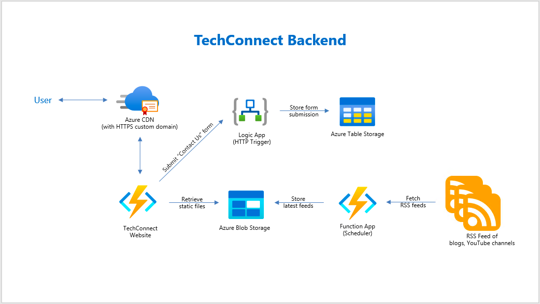
In the August meetup of Azure Community Singapore (ACS), Dileepa Rajapaksa shared with us approaches that we could take to modernise our apps with FaaS (Function as a Service) in Azure where he talked about Azure Functions. After his talk, I decided to share how we could use the knowledge of serverless as well as CDN to help improving our website performance.
The website that we are going to work on today is called TechConnect. It’s a website showing the work done by four of my friends and myself, including our blog posts and YouTube videos. It currently consists of three pages:
In the Articles page, we will list down the most recent blog posts written by all of us. WordPress, Dev.to, and Medium are the three main blog platforms that five of us use. Hence, in order to retrieve the blog posts from these different platforms, we choose to rely on their RSS feed which is available in all the platforms we use.
However, the RSS feed schema varies across different blog platforms. Hence, we have a simple C# program to process the RSS feed and store them as JSON array into a JSON file on Azure Storage. For example, when we are reading the RSS feed from a WordPress blog, we will have the following code to handle its blog post entries.
XNamespace media = "http://search.yahoo.com/mrss/";

var items = xDoc.Descendants("item")
            .Select(i => new BlogFeed {
                Id = i.Element("link").Value,
                Author = blogAuthor,
                Title = i.Element("title").Value,
                ThumbnailUrl = i.Descendants(media + "content").Where(img => !img.Attribute("url").Value.Contains("gravatar.com")).FirstOrDefault()?.Attribute("url").Value,
                Description = i.Element("description").Value,
                PublishedAt = DateTimeOffset.ParseExact(i.Element("pubDate").Value.Replace("GMT", "+00:00"), "ddd, dd MMM yyyy HH:mm:ss zzz", CultureInfo.InvariantCulture)
            })
            .ToList();
Now, where should we put this code at? We can put it in the website project so that every visit to the Articles page will read the feeds from different blogs and do the aggregation. This works fine but it’s going to take a long time to load the web page. For every visit, the web server needs to make several calls over the network to different blog posts to retrieve the RSS feed and then process it before displaying the blog posts on the Articles page.
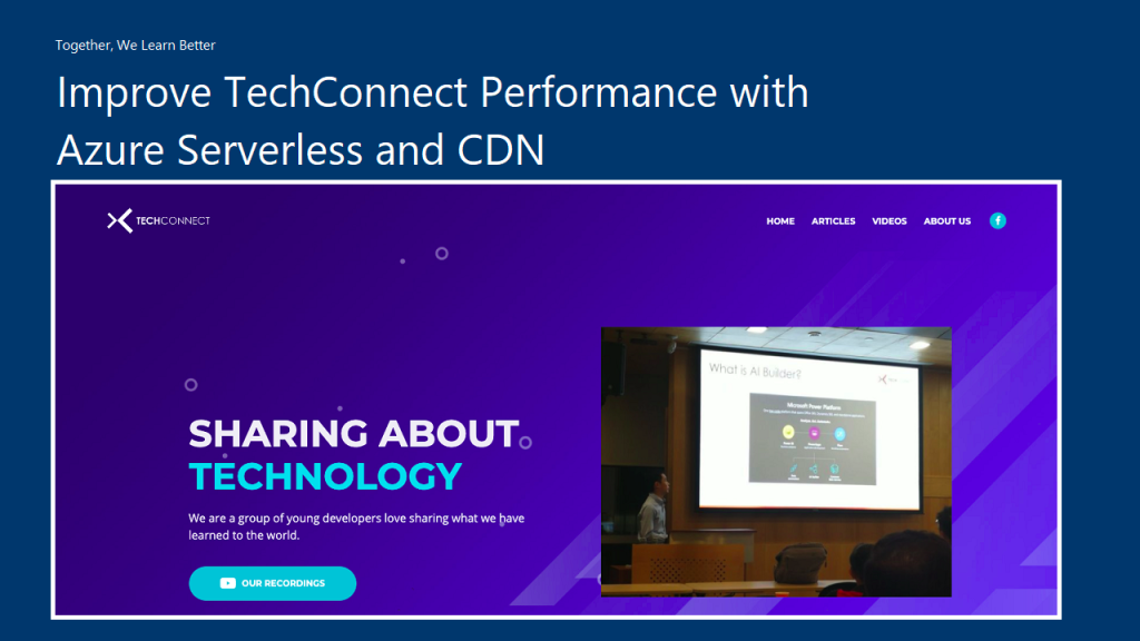
The way we choose is to use Azure Function to retrieve the RSS feed from all the blogs we have in a scheduled manner. We don’t update our blogs frequently, the blogs are at most updated two to three times per day. Hence, we use the time-triggered Azure Function with a call frequency of 6 hours to run the codes above. After each call, the Azure Function will store the info of the latest blog posts into a JSON file and upload it to Azure Storage.
🎨 The workflow of the Azure Function to generate feeds of latest blog posts. 🎨
It’s the same for YouTube videos feed in the Videos page. We can also process the RSS feed from our YouTube channels to retrieve the latest videos information using the codes below.
Since we also don’t publish new videos frequently in a day, we have Azure Function to process the YouTube RSS feeds with the codes above and store the information of our latest videos into a JSON file on Azure Storage.
Azure CDN
There is an advantage of storing the latest blog posts and videos information on Azure Storage, i.e. introducing the Azure CDN (Content Delivery Network). Azure CDN is a global CDN solution for delivering content from the closest POP server and thus accelerate the content delivery of a website.
With Azure CDN, we can cache static objects loaded from the Azure Storage as well.
🎨 PageSpeed Insights for the homepage of TechConnect. 🎨
Azure CDN Standard from Microsoft and Akamai
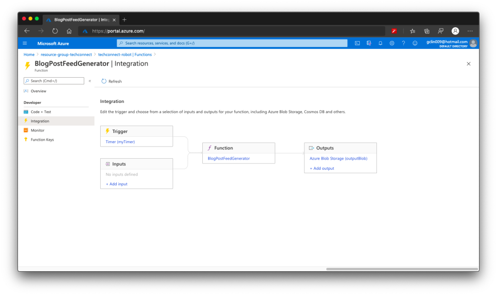
There are three companies offering CDN service in Azure, i.e. Microsoft, Akamai, and Verizon. So far I have only tried out the Azure CDN Standard from Microsoft and Akamai. Eventually the product that I use for TechConnect is Azure CDN Standard from Microsoft.
Why? This is because out of the three companies, Microsoft is the only one providing features that allow me to easily perform the following operations.
Performing URL Rewrite/Redirect;
Updating Cache Header/Settings;
Customising rule-based content delivery.
🎨 Configuring cache expiration and CORS (for production and localhost) in Rules Engine of the Azure CDN Standard from Microsoft. 🎨
These features are currently only available in Azure CDN Standard from Microsoft, but not from Akamai and Verizon. However, if you are willing to pay more to upgrade Azure CDN Standard from Verizon to its Premium edition, then you still can enjoy the features above.
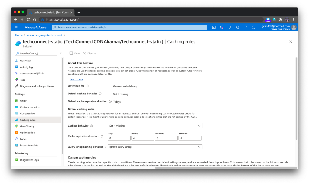
In the previous screenshot, you will notice that there is this Global Rule on top of other rules. The cache expiration is being set there. However, for the Akamai version, we need to set the cache expiration differently under Caching Rules, as shown in the following screenshot.
🎨 Global caching rules settings in Azure CDN Standard from Akamai. 🎨
In the Akamai version, we can set the Custom Caching Rules as well, as shown above. For the Microsoft version, we can do that as well under its rule-based engine.
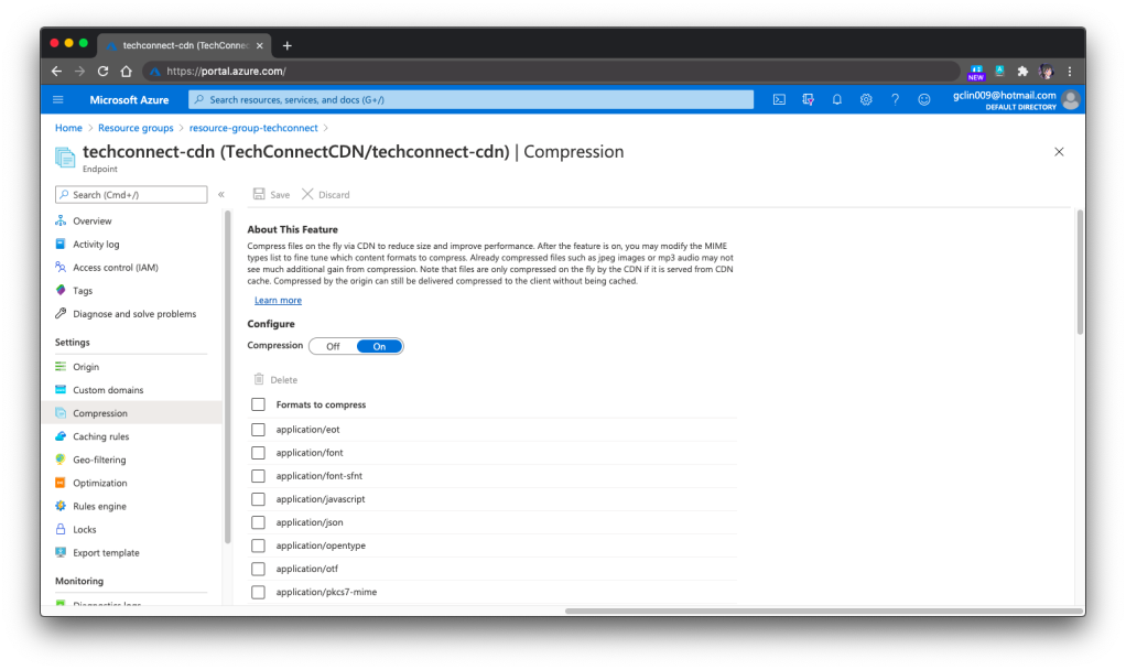
One last important feature that I would like to share is specifying the files that need to be compressed on the fly via Azure CDN so that the performance can be improved. This compression feature is the same in both Microsoft and Akamai versions.
🎨 Compression of files via Azure CDN. 🎨
Azure CDN with Custom Domain and HTTPS
Besides static content, we can also integrate our Azure Web App with Azure CDN. Under the Networking section of a web app, we are able to configure Azure CDN for our web app directly.
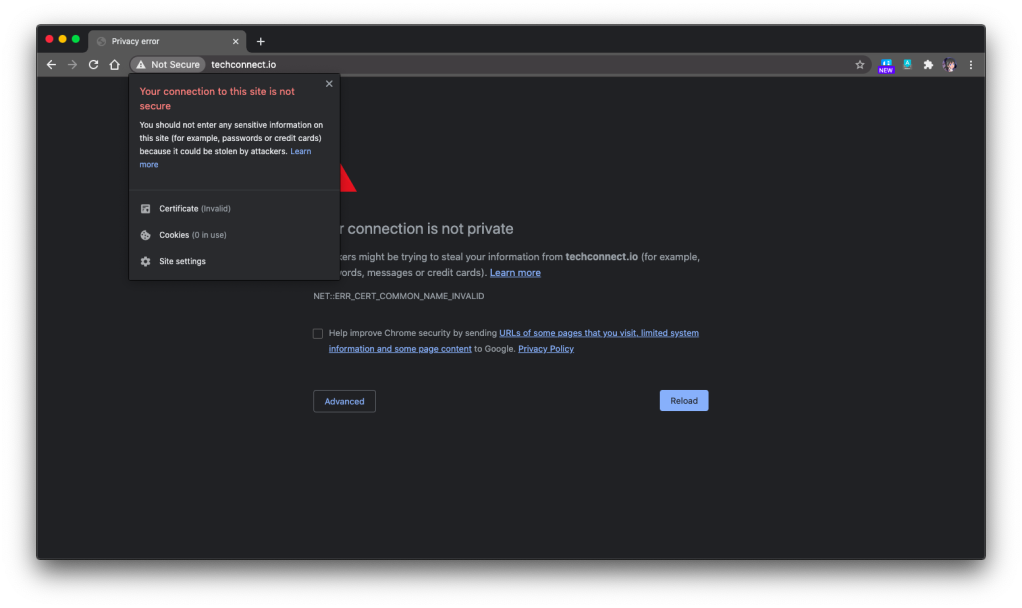
However, there is one important thing to take note if you have a custom domain for the web app and it needs to be HTTPS. Marvin, Eng Teong, and I were trying to set it up with the free SSL cert from SSL For Free, the free cert just did not work with the Azure CDN, as shown in the following screenshot. So far we still have no idea why. If you happen to know the reason, please let me know. Thank you!
🎨 Insecured connection to the website via Azure CDN. 🎨
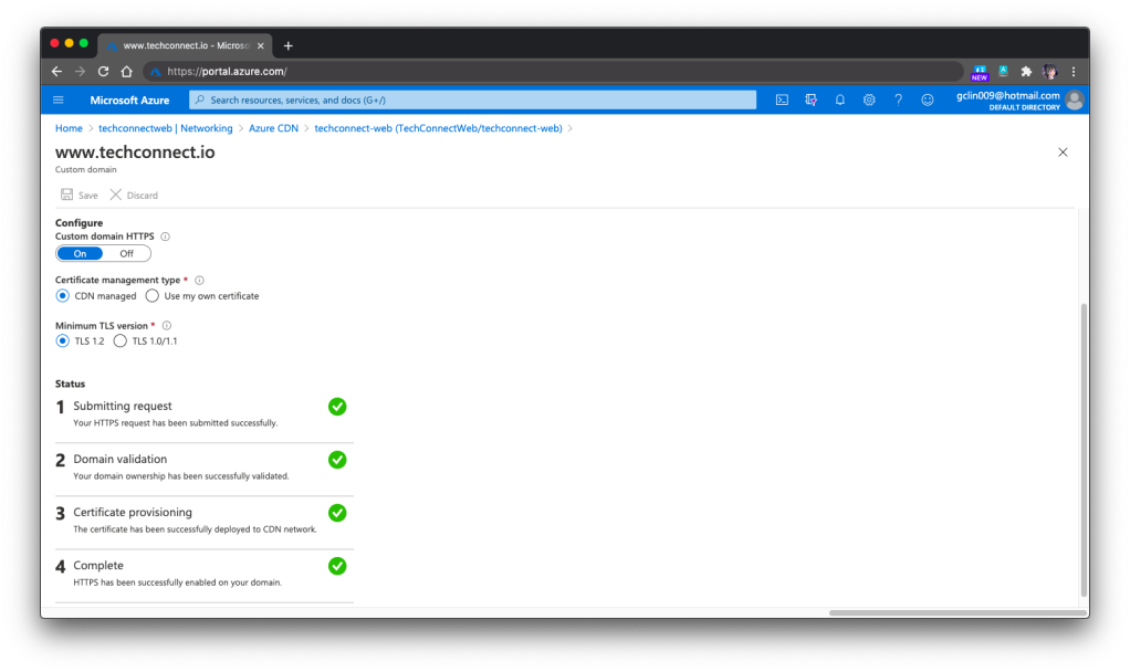
For https://www.techconnect.io, we successfully setup the HTTPS for Azure CDN of TechConnect using the CDN-managed certificates. Hence, currently visitors have to visit the website through https://www.techconnect.io.
🎨 Successfully setup HTTPS for our custom domain with www. 🎨
One more thing that we need to take note of is that if we choose to bring our own certificates for Azure CDN, that those certificates must be stored in Azure Key Vault first.
However, after storing the certificates in the Key Vault, we also need to remember to setup the right permissions for the Azure CDN to access those certificates in the Key Vault. To do so, we need to run the following command in Azure CLI or Azure Cloud Shell to create a new Azure Service Principal for that purpose.
This command is normally available in the HTTPS setup page of the Azure CLI. So simply have your administrator of the directory to run the command above will be fine.
Here, I’d also like to thank Eng Teong for helping me in this step.
Simple Contact Us Form with Logic App
For the Contact Us form on the TechConnect homepage, it’s a perfect example of small little things that is crucial in a system but can be solved with easy solution. Of course, we can use some ready-made solutions available in the market to help us manage the Contact Us form. However, that means we rely on 3rd party services and our data most likely will not be with us.
So, if you are looking for a simpler solution, I’d like to recommend you to give Azure Logic Apps a try.
Here, I will not go through the details about Logic App and steps on how to set it up. There are plenty of tutorials about this online. Instead, I will share with you our design of Logic App for the Contact Us form on TechConnect.
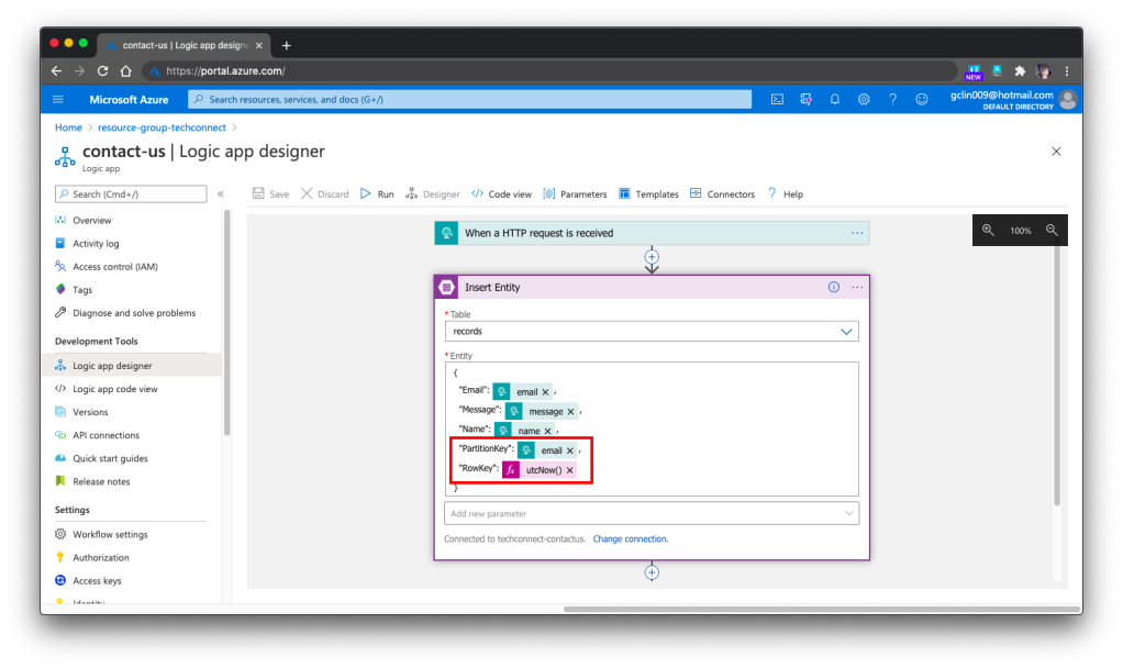
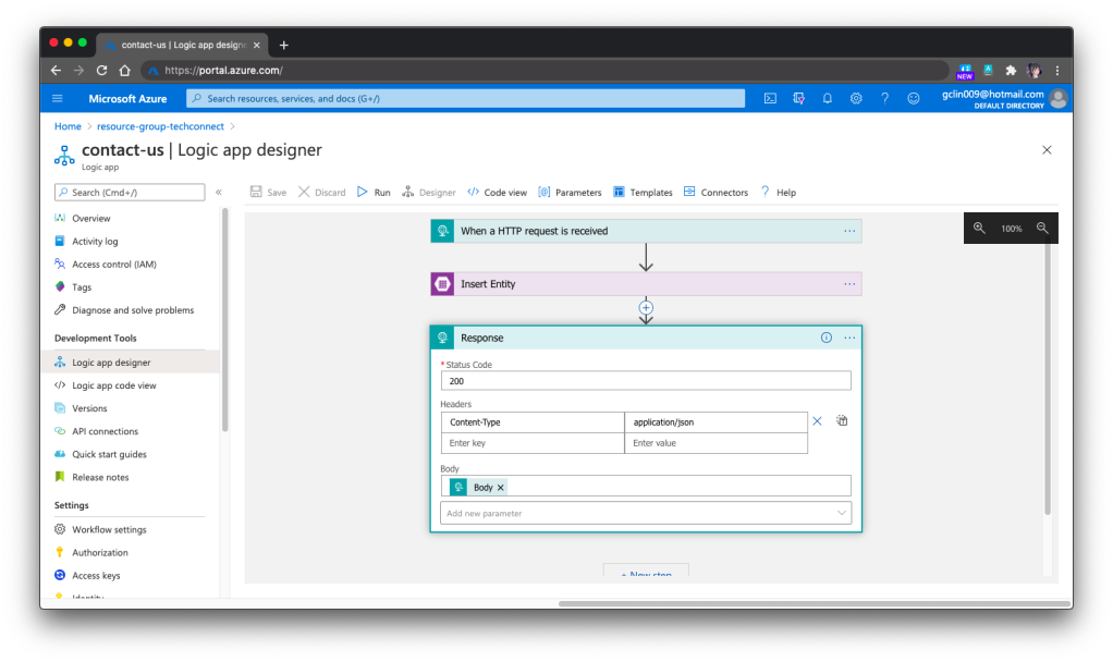
Our Logic App is HTTP triggered. Once it receives a POST request, it will validate the request body against the schema provided. If the request is valid, it will proceed to insert the form submission to the Azure Table Storage, a NoSQL key-value store. Finally, it will return a HTTP 200 back.
🎨 The overall design of our Logic App for TechConnect Contact Us form. 🎨
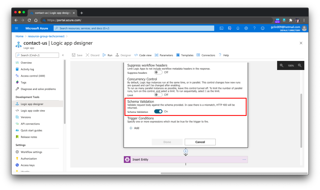
Just now we mention about schema validation for the HTTP request body but how to do so? It turns out that it’s pretty straightforward, just need to turn on the feature in the Settings of the 1st Step, as shown in the following screenshot.
🎨 Turned on the Schema Validation for HTTP requests. 🎨
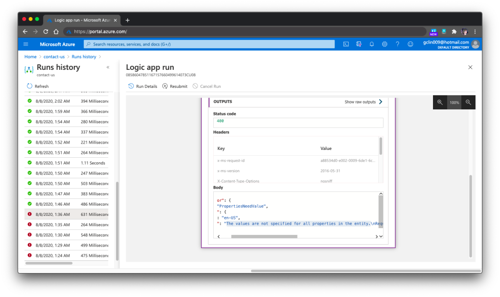
Finally, we need to talk a bit about how to debug the Logic Apps. One the Azure Portal, there is a very helpful tool for debugging and tracing purposes. The tool is called the Runs History which is available right in the Logic App Overview page. You can refer to the official Microsoft Docs for more details about it.
🎨 Run History and the message on why the selected Run failed. 🎨
For example, when we omitted the PartitionKey and RowKey in the Step 2, we would see Step 3 is not executed in the Run History and it stopped at the Step 2. Then the detail error message will be available there to give us more info, as shown in the screenshot above.
Conclusion
That’s all for the weekend project that I did with the help from my friends, Marvin and Eng Teong.
Lastly, please visit our TechConnect website and say hi to us! =D
On 30th July, I’m glad to attend the webinar “Percolation Framework for Loss Distribution of Smart Contract Risks”, which is organised by National University of Singapore.
Assistance Prof. Petar Jevtić from Arizona State University is invited as the webinar key speaker. Prof Jevtić’s research focus is on the modelling of risk with primary applications in Actuarial Science and Mathematical Finance. During the webinar, he shared with us his work done together with Nicolas Lanchier. Since the topic is related to Smart Contracts, in the beginning of his talk, he gave us a clear definition of Smart Contract from Nick Szabo.
For those who have been following Blockchain news, the name “Nick Szabo” should sound familiar because Nick Szabo is the computer scientist known for research in digital currency. Most importantly, although he has repeatedly denied it, people suspect that he is the bitcoin founder, Satoshi Nakamoto.
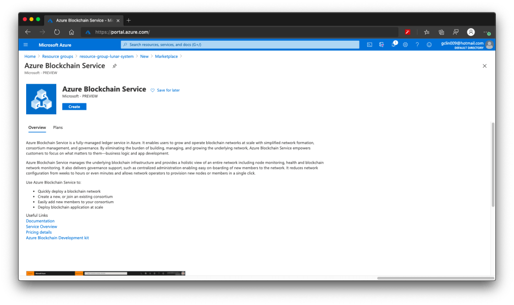
ABS is a fully-managed ledger service in Azure announced in May 2019. With ABS, customers do not need to worry about developing and maintaining the underlying blockchain infrastructure.
🎨 Azure Blockchain Service is still in preview in July 2020. 🎨
There are a few things that I’d like to share regarding the ABS, even though it is still in preview now (as of July 2020).
Firstly, currently the ABS is supported only in a few regions, such as Southeast Asia, West Europe, East US, and so on, as shown in the following screenshot.
🎨 The supported regions in Azure Blockchain Service. 🎨
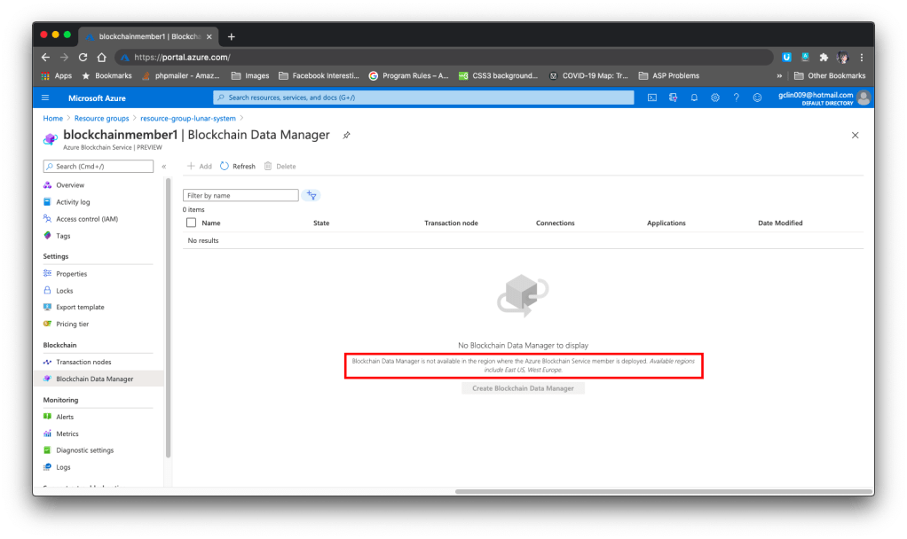
However, if we would like to capture, transform, and delivers transaction data using the Blockchain Data Service, then we have to be extra careful in choosing the region. As of July 2020, Blockchain Data Manager is only available in the East US and West Europe regions. Hence, if we choose any region outside of the two, we will not be able to access the Blockchain Data Manager, as shown in the screenshot below.
🎨 Blockchain Data Manager is only available in the East US and West Europe regions. 🎨
Hence, we need to know that currently ABS supports only Quorum as the ledger protocol.
Thirdly, if we would like to have some sample codes on how to interact with the transaction nodes on the blockchain, there are a few samples available on the Azure Portal where we can refer to, as shown in the following screenshot.
🎨 Sample codes on how to connect to the transaction node. 🎨
Currently it takes about 10 minutes to create an ABS successfully on the Azure Portal.
Local Deployment of Smart Contracts, Problems Encountered, and GitHub Issues
With the Azure Blockchain Development Kit for Ethereum extension, we can connect to the ABS consortium from the Visual Studio Code. With the development kit, developers can easily create, connect, build, and deploy smart contracts locally.
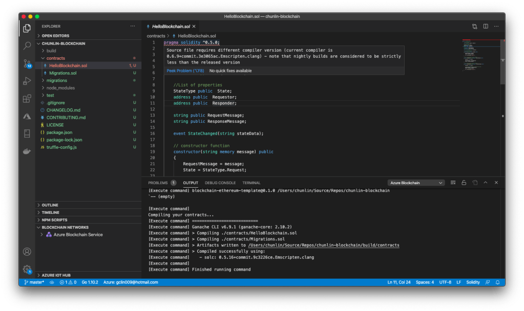
As mentioned in the Microsoft Docs, the programming language used to implement Smart Contracts are Solidity. The first problem comes from here. In the new Solidity project created by the development kit, the sample HelloBlockchain as well as the Migrations files are having some issues.
🎨 Error happens in the line having pragma keyword. 🎨
Firstly, there is an issue regarding the compiler version, as highlighted in the first line that starts with Pragma keyword in the screenshot above.
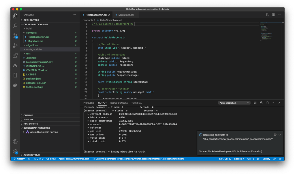
Trust in smart contract can be better established if their source code is available. Since making source code available always touches on legal problems with regards to copyright, the Solidity compiler encourages the use of machine-readable SPDX license identifiers. Every source file should start with a comment indicating its license…
Hence, we need to add the SPDX license identifier at the top of Solidity files, for example
// SPDX-License-Identifier: MIT
Now, we can proceed to build and deploy the Smart Contract.
🎨 Deploying contracts to the cloud. 🎨
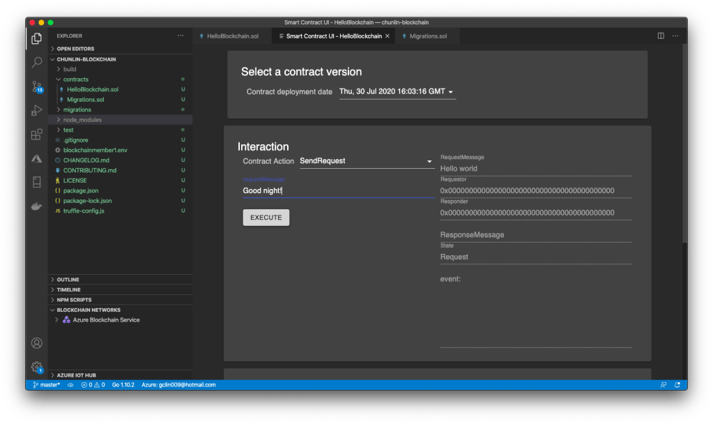
According to the Microsoft Docs, we should be able to use the Smart Contract UI provided in the Visual Studio Code to call the contract functions. However, it is not possible at all if we have deployed the Smart Contracts to the Azure.
🎨 The Smart Contract UI. It will show “method handler crashed” if the Smart Contract is on ABS. 🎨
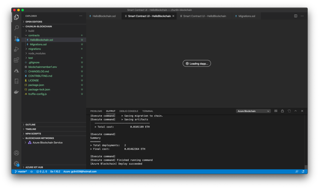
Now here comes the fourth problem. When I launched the VS Code again, I could no longer get the Smart Contract UI back even though I redeploy the Smart Contract to local instead of ABS. VS Code will simply keep showing the message “Loading dapp…”, as shown in the screenshot below.
Currently the issues highlighted above are new. The last one was just raised about two weeks when I am writing this article. So, if you have any new findings or doubts, please always let us know on the GitHub Issues of the project.
That’s all for my journey with Azure Blockchain Service which is still in preview and very young.
By the way, Mark Russinovich did a very good introductory presentation on what blockchain is. If you are interested in blockchain and would like to have a quick overview about this cool technology, please watch the YouTube video below.